In mechanical engineering, tolerances define how much a part’s actual dimensions can vary from what’s specified on the drawing. These small allowances might seem minor, but they’re crucial for making sure a finished part actually works as intended, especially when it’s meant to fit with other components in an assembly.
Skipping tolerances—particularly in areas that really matter can easily lead to parts that simply don’t function as designed. Every manufacturing process introduces some level of inaccuracy, so expecting perfection just isn’t realistic.
On the other hand, when tolerances are set thoughtfully, manufacturers know exactly where to focus their efforts. Paying extra attention to those critical spots during production often means the difference between smooth assembly and a pile of unusable scrap. It’s not just a technicality; it’s a practical step that keeps projects on track and saves both time and material.
What is Tolerance in Engineering?
When it comes to dimensions in manufacturing, tolerance simply refers to how much a measurement is allowed to vary. Basically, it’s the gap between the largest and smallest acceptable sizes for a part.
Since it’s just not realistic to expect every single piece to be made to a perfectly exact size, we use tolerances on technical drawings to make sure that parts will fit and function as intended even if they’re a tiny bit off.
This becomes especially important when we’re dealing with parts that need to fit together, like in an assembly. Let’s say you’ve got a slot that’s supposed to fit another component.
Setting tolerances ensures that both pieces will go together smoothly, even if there are slight differences in their actual sizes.
One of the main perks here is the idea of interchangeability if tolerances are set correctly, you can swap out individual parts without worrying that the whole thing won’t work. That’s a huge advantage in production and maintenance.
Tolerances can be expressed in several ways:
- Direct limits, or as tolerance values applied directly to a dimension.
- Geometric tolerances, indicated by special symbols related to part surfaces.
- Notes referring to specific conditions, usually placed next to the corresponding dimensions. Example: single limit tolerance which limits either the maximum or minimum size of a feature or a space, leaving the other limit of size unspecified.
- A general tolerance note in the title block.
You’ll often find general tolerances either mentioned in a note or built right into the title block of a drawing. For example, a typical note might read: “All decimal dimensions to be held to ± .002.” What this actually means is, if you see a dimension like .500 on the drawing, you should treat it as having a tolerance of ± .002. So, the acceptable range would be from .498 up to .502.
If you’re working with metric dimensions, you’ll see something similar—maybe a note that says, “All metric dimensions to be held to ± 0.05.” In that case, a dimension listed as 65.00 would have a tolerance range between 64.95 and 65.05.
The important thing here is that the tolerance gets applied automatically to each feature, simply based on what’s written for the dimension. Now, keep in mind, actual tolerances might be a bit different depending on which company you’re dealing with, but these numbers are pretty standard for machined parts.
Also, if every dimension on your drawing has the same number of decimal places, the general tolerance might just include a single set of figures no need to list out a bunch of different tolerances.
But here’s something you don’t want to miss: if a specific tolerance is listed right next to a dimension, that one always takes priority over the general tolerance note. No matter what the standard tolerance is, the added tolerance directly on the dimension is the one you should follow—even if it happens to be a bit looser than the standard.
Direct Limits
When it comes to specifying tolerances on dimensioned features, one straightforward way is to use limit dimensioning. This is actually the method recommended by ASME. With limit dimensioning, you show both the largest and smallest acceptable sizes right there with the dimension itself.
You might see this presented in a couple of ways: sometimes the higher value is listed above the lower one, making it easy to compare. Other times, especially if everything’s written out on one line, the smaller limit comes first, followed by the larger one either separated by a dash or a slash. For example, you might write 3.49-3.53 or 3.49/3.53.
Plus, and Minus Tolerances
In this method, you start by stating the basic size, then add a plus or minus sign along with the tolerance value.
Tolerances themselves can be either unilateral or bilateral. With a unilateral tolerance, the allowed variation occurs only on one side of the basic size so you’re only accounting for deviation in a single direction.
In contrast, bilateral tolerance lets the dimension shift on either side of the basic size, giving a range above and below the nominal value.
Now, when the allowed variation is the same in both directions, you’ll see the plus sign before the value. This plus-minus notation really only applies if those upper and lower limits are identical. So, if both the positive and negative deviations match, the plus and minus format works perfectly.
Important terms
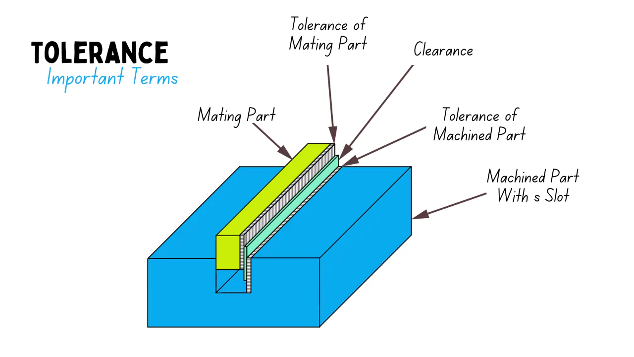
The figure shows a system of two machined parts with slot and mating parts that have toleranced dimensions. These two parts are used as examples in ASME/ANSI standard to define important terms.
- Nominal Size: This refers to a general or commonly used measurement, typically expressed as a simple fraction. It serves as a convenient label rather than an exact value.
- Basic Size: The basic size is essentially a theoretical measurement, used as the starting point when tolerances are being set. On technical drawings, you’ll usually find this size highlighted inside a rectangular box, making it clear that this is the key reference dimension.
- Actual Size: After machining is complete, the finished part is measured, and this measurement is known as the actual size. It represents the real, physical dimension of the component.
- Limits of Size: For any part, there are specific boundaries that its measurement must fall within the maximum and minimum allowable sizes. The upper limit is the largest value permitted, while the lower limit is the smallest. The actual size needs to stay within these two boundaries.
- Allowance: Allowance describes the minimum possible clearance or the maximum permissible interference between two mating parts. In other words, it’s the tightest fit that’s allowed for the parts to function as intended.
Considerations when setting tolerances
One of the main challenges in engineering is figuring out just how much flexibility you can allow in your tolerances before it starts to affect other aspects of the process or the final result.
Getting this right usually involves a mix of scientific reasoning, hands-on engineering know-how, and real-world experience. Often, running experiments like carefully planned tests or thorough engineering assessments plays a big role in showing how different tolerances actually impact outcomes.
Now, it’s important to remember that just because you specify tight engineering tolerances, it doesn’t mean everything coming off the production line will automatically meet those specs.
Every system or manufacturing process brings a certain amount of natural variation, both in what you put in and what comes out the other end.
There’s also no escaping the fact that every measurement comes with some degree of error and uncertainty. For example, when your data falls into a normal distribution, you’ll sometimes see values way out in the tails well past three standard deviations from the average.
In practice, this means some measurements could easily fall outside your specified tolerance limits, even if most are right on target.
Because of this, the capabilities of your materials, processes, and systems need to be in sync with whatever tolerances you set. It’s not just about setting the right numbers strong process controls and a solid quality management approach, like Total Quality Management, are crucial for keeping things on track and within the limits you want.
To keep tabs on how well a process is sticking to its tolerances, engineers often rely on a process capability index. This handy metric lets you compare your tolerances directly against what’s actually happening in production.
Finally, deciding on the right tolerances isn’t just a technical call it’s also influenced by your approach to sampling and quality checks.
For instance, your chosen statistical sampling plan and your Acceptable Quality Level can determine whether you need extremely strict tolerances, aiming for virtually perfect conformance, or if you’re comfortable allowing the occasional part to slip through that doesn’t quite meet the mark.
Types of Tolerances
Currently, geometric tolerances are represented by 14 different symbols, but if we classify them by type, there are actually 15 distinct categories.
These tolerances are generally organized into four main groups: form tolerance, orientation tolerance, location tolerance, and run-out tolerance. By using these categories, it’s possible to specify requirements for virtually any geometric shape.
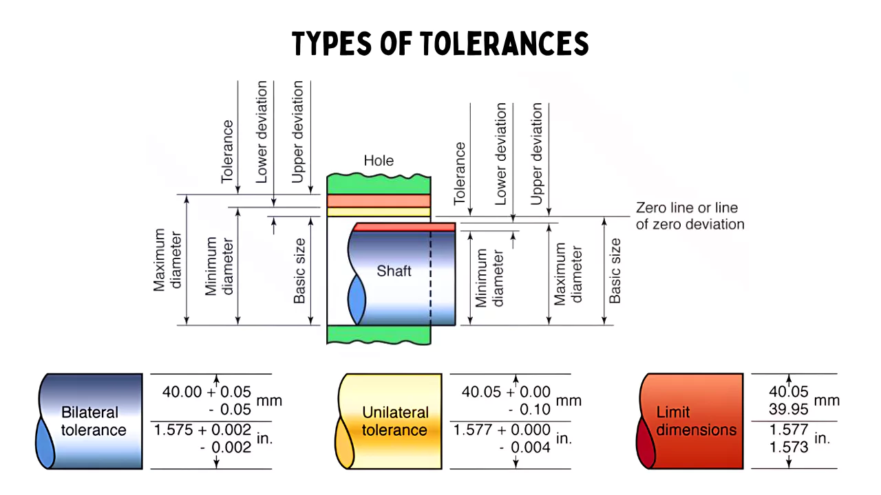
Following are the three types of tolerances used in measurements:
- Unilateral tolerances
- Bilateral tolerances
- Compound tolerances.
1. Unilateral Tolerances
If both limit dimensions are positioned exclusively either above or below the nominal size—like you can see in the accompanying figure—then the tolerance applied in this case is referred to as unilateral tolerance.
2. Bilateral Tolerances
When both the upper and lower limits of a dimension are specified on either side of the nominal size, the tolerances involved are referred to as bilateral. In other words, the allowed variation extends both above and below the intended measurement.
3. Compound Tolerances
Compound tolerance refers to a situation where multiple types of tolerances are combined to define the allowable variation for a particular feature. In other words, it arises when established tolerances such as angular or lateral tolerances—interact and collectively influence a single dimension or aspect of a component.
For instance, let’s consider a case where the tolerance for a particular length (let’s call it ‘l’) depends on the tolerances applied to the dimensions L, h, and the angle θ. Here, the total or compound tolerance for ‘l’ reflects the combined impact of variations in these three parameters.
Specifically, the minimum possible value for ‘l’ would occur when L is at its lower limit (L–b), θ is at its upper limit (θ+α), and h is at its upper limit (h+c).
This example illustrates how compound tolerance is not simply about stacking numbers, but about understanding how different sources of variation come together to affect the final outcome.
Fits
When you’re dealing with engineered products, it’s pretty common for parts to need to fit together just right—sometimes sliding smoothly into place, other times locking in tightly so everything works as it should. This is where the concept of “fit” comes in.
Essentially, fit refers to how the dimensions of different components—like a hole and a shaft—relate to each other, especially when they’re supposed to share the same basic size but fall within certain tolerance zones. Whether things end up snug or with a bit of play depends on these precise relationships.
Getting the right fit isn’t just about matching up a hole with a shaft; there are lots of options for how they can come together, and picking the correct mechanical tolerances is key. Plus, engineers can’t just focus on numbers alone.
They also have to consider how easy the parts will be to assemble, the environment they’ll be working in, and just how precise everything needs to be. All these factors come together whenever components are designed to work as part of a bigger assembly.
Common Types Of Fits
The International Organization for Standardization (ISO) recognizes several types of fits within mechanical engineering, each designed for specific scenarios. Understanding these fit types is essential, as choosing the right one can significantly impact the performance and reliability of a mechanical assembly. Here are the primary categories of fits:
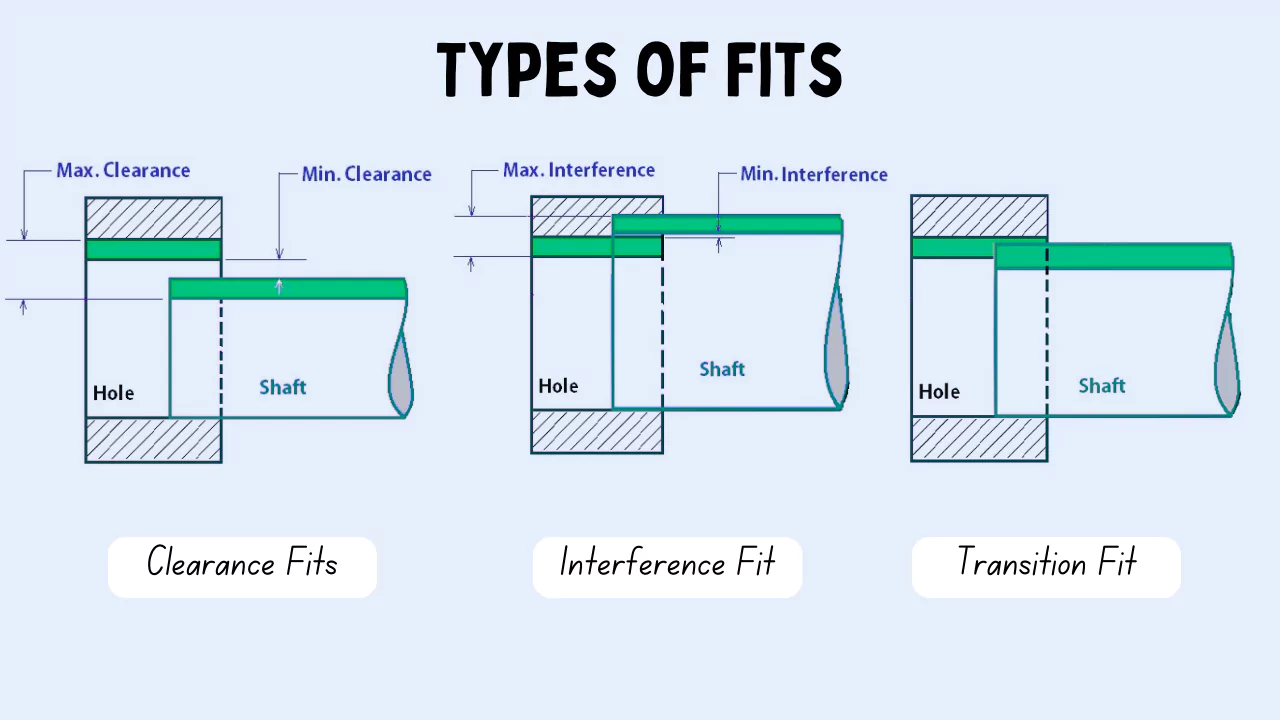
Clearance Fit
A clearance fit is typically chosen when parts need to move freely relative to one another. You’ll see this kind of fit used in assemblies where it’s important that components can slide in and out without resistance. Essentially, the main goal here is to allow for easy movement between joined parts.
In practice, this fit is achieved by making the shaft just a bit smaller than the hole it fits into. This size difference creates two main clearance scenarios.
The first is called minimum clearance, which occurs when the shaft is at its largest allowable size and the hole is at its smallest meaning the parts still fit together, but just barely.
The other scenario is maximum clearance, where the shaft is at its smallest and the hole is at its largest, allowing the greatest amount of space between them. Both situations ensure that the components won’t get stuck and can move as needed within the assembly.
Interference Fit
Interference fit—sometimes referred to as friction fit or press fit—is a method of joining two components by forcing them together so that they hold without additional fasteners.
The key idea is that one part is slightly larger than the other, and assembly requires a certain amount of force to push them together. This tight physical fit is what keeps the parts securely joined.
There are different types of interference fits, and the specific method used often depends on the kind of force or technique applied during assembly. A classic example of this approach is pressing a bearing into its housing. In such cases, the bearing is just a bit bigger than the housing hole, so it has to be pressed in firmly, creating a secure connection.
When it comes to measuring interference, there are two key values to consider. The maximum interference refers to the difference between the smallest possible diameter of the hole and the largest possible diameter of the shaft.
In contrast, the minimum interference is calculated as the difference between the smallest diameter of the shaft and the largest diameter of the hole. These measurements help determine how tight the fit will be, ensuring the assembly performs as intended.
Transition Fit
Transition fits occupy a middle ground between interference fits and clearance fits, offering a practical compromise for situations where precision in manufacturing is essential.
These fits are particularly valuable when you need to bring two components together with a higher degree of accuracy—think, for instance, of installing a piston inside a cylinder.
In this case, the piston’s diameter is intentionally made slightly smaller than the cylinder bore. This slight difference leaves just enough clearance to make assembly manageable, while still allowing a bit of interference to keep everything securely in place and stable.
In the workshop, you’ll often hear transition fits referred to as “slip fits” or “push fits.” What’s distinctive about them is the combination of minimal clearance and subtle interference.
This balance not only makes the assembly process more straightforward but also helps maintain the stability and alignment of the joined parts. For engineers and designers looking to create connections that are both reliable and easy to assemble, transition fits often turn out to be the go-to solution.
FAQs
What is meant by tolerance in engineering?
Tolerance is the total amount a dimension may vary and is the difference between the upper (maximum) and lower (minimum) limits. Because it is impossible to make everything to an exact size, tolerances are used on production drawings to control the parts.
Why is engineering tolerance important?
Because it is impossible to make everything to an exact size, tolerances are used on production drawings to control the parts. When do we need tolerances? In particular, tolerances are assigned to mating parts in an assembly. For example, in case, when the slot in the part must accommodate another part.
What does high tolerance mean in engineering?
A high tolerance means the allowable variation from the nominal or target dimension is very small. In other words, the manufactured part must closely match its design specifications with minimal standard deviation.
What is the importance of tolerance in electrical engineering?
In engineering, tolerance is important because some variation in manufactured goods is normal and expected. Calculating the amount of allowable variance saves time, materials, and money while still engineering high-quality products.
How to find tolerance in engineering?
1. Calculating Total Tolerance.
2. Total Part Tolerance = Upper Limit – Lower Limit.
3. Calculating Fit between Two Objects.
4. Allowance = Lower Limit of the Hole – Upper Limit of the Pin.
NOTE: Formula should always start as stated in order to get correct outcomes.
5. Positive (+) Allowance = Clearance.
What is a tight tolerance in engineering?
Tight tolerance can mean something different depending on the molder, but it is generally recognized as ± 0.002 inches, and very tight tolerance is ± 0.001 inches. Part complexity, material, manufacturing processes, and tooling all impact the tolerances that can be achieved.