What is an Electric Motor?
An electric motor serves as a device that converts electrical energy into mechanical motion. This transformation happens when electrical current moves through coils of wire within the motor, generating a magnetic field that produces torque—the force that causes the shaft to rotate.
On the other hand, an electrical generator performs the reverse operation. While it shares similarities with a motor in terms of design, its primary function is to turn mechanical energy into electrical energy.
Electric motors can draw their power from either direct current (DC) or alternating current (AC) sources, depending on the specific design. Typical sources include batteries, rectifiers, the power grid, generators, or inverters. Motors are often classified by their power supply type, intended use, construction details, or the kind of output they deliver.
In terms of design, motors may operate using DC or AC, and they can be either brushed or brushless. They also vary by the number of phases—ranging from single-phase to three-phase systems—and by the direction of their magnetic flux, whether radial or axial. Cooling methods differ as well; some rely on air, while others use liquid for temperature control.
You’ll encounter standard electric motors across a wide range of industrial settings. They power everything from blowers and pumps to fans, machine tools, household appliances, disk drives, and vehicles.
Smaller versions are found in applications like electric watches. Notably, electric motors can sometimes be used in reverse as generators. For example, traction motors in vehicles can reclaim otherwise wasted energy—such as during regenerative braking—converting mechanical energy back into electricity rather than letting it dissipate as heat or friction.
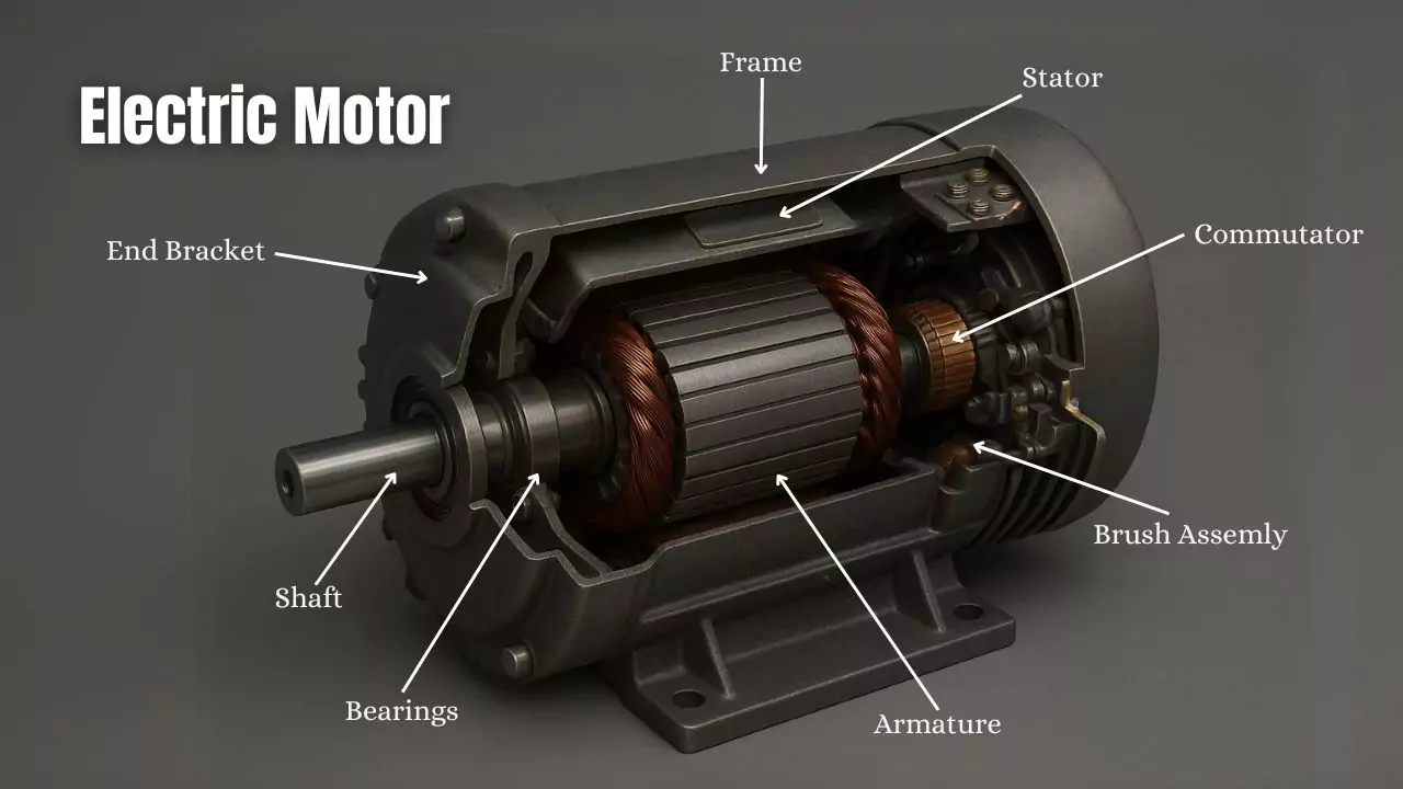
Parts of an Electric Motor
An electric motor consists primarily of two mechanical elements: the stator, which remains stationary, and the rotor, which turns during operation. From an electrical perspective, the main components are the field magnets and the armature. The conductors, or windings, are split between the stator and rotor, creating a complete magnetic circuit within the motor.
Field magnets—whether they are permanent magnets or electromagnets—establish the magnetic field that interacts with the windings. In most motor designs, these magnets are mounted on the stator while the windings are situated on the rotor. However, it’s worth noting that certain motor types reverse this arrangement, placing the windings on the stator and the magnets on the rotor instead.
Role of Bearings in Electric Motors
Bearings serve a crucial role in supporting the rotor, enabling it to rotate smoothly along its axis. These components are situated within the motor housing, where the motor casing itself provides structural support for the bearings.
The Electric Motor Rotor
The rotor, which serves as the moving component within an electric motor, is ultimately responsible for delivering mechanical power. In most cases, the rotor is built with conductors that carry electrical current; as these conductors interact with the stator’s magnetic field, they generate the torque that turns the rotor’s shaft.
Rotor design can vary significantly. In some motors, permanent magnets are incorporated into the rotor itself, while the conductors are positioned within the stator. This arrangement can be advantageous from an electrical perspective, as permanent magnets are well-suited to operate efficiently across a broad range of speeds and power levels.
One detail that often goes overlooked is the air gap between the rotor and the stator. This gap is essential, providing just enough clearance for the rotor to rotate freely. However, its size is more than a simple design consideration—it has a direct impact on the motor’s electrical performance.
Generally, a narrower air gap leads to better efficiency and an improved power factor, while a wider gap increases the current required to energize the motor and lowers the power factor.
That said, shrinking the air gap too much can create its own set of problems, such as mechanical interference, greater losses, and increased noise during operation. It’s a careful balance.
The rotor shaft itself extends through the bearings and projects out from the motor, forming the point where the load is attached. When the force from the load is applied beyond the outermost bearing, it creates what’s known as an overhung load—a factor that engineers have to account for in the overall design.
The Electric Motor Stator
The stator, positioned around the rotor, typically houses the field magnets. These magnets can either be electromagnets—created by winding wire around an iron core—or permanent magnets, depending on the motor’s design.
The role of these magnets is to establish the magnetic field, which then interacts with the windings on the rotor, generating the necessary force for operation. The stator’s iron core is constructed from thin, insulated sheets of metal. By separating each layer with insulation, energy loss is significantly minimized.
This process of lamination is a proven method for reducing the losses that would otherwise occur in a solid iron core. In the case of motors that incorporate built-in permanent magnets—such as those with resin-packed designs commonly seen in various devices—the use of plastic compounds not only helps in securing the magnets but also contributes to quieter performance by dampening vibrations and noise.
The Electric Motor Armature
The armature is formed by winding wire around a core made of ferromagnetic material. When current passes through these windings, a magnetic field is generated, resulting in a Lorentz force that acts on the armature. This force turns the rotor, converting electrical energy into mechanical motion.
Typically, these windings take the shape of coils placed over a laminated iron core. As current flows, magnetic poles are established in the core. Depending on design, electric motors can be classified as either salient pole or non-salient pole types.
With salient-pole motors, both the rotor and stator are constructed so that distinct poles protrude from the core. These poles are wound with wire, and when energized, each one becomes either a north or south magnetic pole.
On the other hand, non-salient-pole motors—sometimes called round-rotor or distributed field motors—use a rotor with a smooth, cylindrical core. Here, the winding is distributed evenly around the core, rather than concentrated on protruding poles.
As alternating current flows through the windings, it continuously creates and shifts magnetic poles within the motor, which keeps the rotor turning.
A shaded-pole motor is a particular design where part of each pole is wrapped with an auxiliary winding. This setup causes a phase shift in the magnetic field for that pole, enabling the motor to start and run with a single-phase supply.
Electric Motor Commutator
A commutator serves as a rotary switching mechanism designed to deliver either alternating current (AC) or direct current (DC) to the rotor, while periodically altering the current within the rotor windings as the shaft rotates. Structurally, it consists of a cylindrical assembly made up of metal segments attached to the armature.
Conductive brushes, typically crafted from carbon, are positioned against the commutator to maintain a continuous sliding electrical connection, enabling current flow to the rotor.
One critical function of the commutator is its ability to reverse the current direction in the rotor windings with every half rotation (i.e., every 180 degrees). This reversal is essential because it ensures the torque generated by the rotor remains consistent in direction. If a commutator were absent, the torque direction would shift every half-turn, causing the rotor to oscillate rather than rotate smoothly, ultimately resulting in a stall.
Recent developments in motor technology suggest that commutator-based motors may eventually be phased out in favor of brushless DC motors, induction motors, and permanent magnet motors. This shift is primarily due to the inherent energy losses and maintenance demands associated with traditional commutator designs.
Mechanics of How an Electric Motor Works
Electric motors operate by converting electrical energy—whether supplied as alternating current (AC) or direct current (DC)—into mechanical energy, which then produces motion. At the core of this process is the interaction between the electric current that passes through the windings (the coils) and the magnetic field that these coils generate.
It’s worth noting that as the electric current increases, the magnetic field produced by the coil also becomes stronger. According to Ohm’s Law (V = R × I), if the resistance (R) in the circuit rises but you wish to keep the current (I) at the same level, the voltage (V) applied must be increased accordingly.
Types Of Electric Motors
The types of electric motors are:
DC Motors
A DC motor is an electromechanical device that transforms electrical energy—specifically from a direct current (DC) source—into mechanical motion. The underlying principle behind its operation lies in the interplay of magnetic fields generated within or around the motor’s components.
Most DC motors feature either electronic or electromechanical mechanisms designed to reverse the direction of current as needed for proper functioning. Historically, DC motors were among the earliest motor types put to practical use, largely because they could draw power directly from the DC lighting and distribution systems common in early electrical installations.
One of the notable advantages of DC motors is their flexible speed control. This can be achieved by adjusting the supply voltage or by altering the current flowing through the field windings, offering a wide operational range. For this reason, small DC motors are a common choice in everyday items such as household appliances, toys, and various hand tools.
Universal DC motors, known for their lightweight brushed design, can operate on both direct and alternating current. These motors are often selected for portable appliances and tools, thanks to their compatibility with different power supplies.
In modern industry, larger DC motors still play a key role. They are frequently employed in applications like elevators, hoists, electric vehicles, and the heavy-duty rolling mills used in steel production. However, with advancements in power electronics, many applications that once depended on DC motors now use AC motors as alternatives.
12V Motors
A 12V DC motor is often chosen for its compact size and affordability, but despite these features, it can deliver enough output power for a surprising range of applications. One of the practical benefits of operating at 12 volts is the straightforward compatibility with battery power; fewer cells are needed to reach the target voltage, which simplifies power supply considerations.
It is worth noting that higher voltage motors generally perform with greater efficiency over longer run times when used in electronic drive systems. While DC motors are available in a wide range—anything from 1.5V up to 100V—the most common variants tend to be in the 6V, 12V, and 24V categories, especially for basic uses.
When selecting a 12V DC motor, certain technical specifications become especially important: torque, speed, power output, and power consumption all play a role in matching the motor to its intended job. In most cases, a 12V DC motor is brushless, meaning it does not rely on brushes to transfer current. This design choice is intentional, as brushless motors sidestep many of the maintenance headaches and inefficiencies often seen in brushed versions.
Brushed motors, for instance, can be more complicated and introduce their own set of challenges. By contrast, the brushless 12V motor streamlines things, reducing both wear and the potential for electrical noise.
Looking inside a brushless 12V DC motor, you will find several key components: an external rotor fitted with permanent magnets, usually three coils (though the exact configuration can vary), electronic commutation systems, drive electronics, and a range of sensors. Unlike their brushed counterparts, these motors use sensors—such as Hall Effect sensors—to regulate the current and control motor function.
It is also worth mentioning that while the overwhelming majority of 12V motors are DC, there are still a handful out there based on AC technology. However, for most practical purposes, when someone refers to a 12V motor, they almost always mean a DC type.
Brushless Motor
A brushless motor, often labeled as a BL motor or BLDC (Brushless Direct Current) motor, is sometimes also known as an electronically commutated motor (ECM). Despite these different terms, all refer to a specific category of DC motors. It is worth noting that brushless motors may also be described as synchronous DC motors.
In operation, a brushless motor relies on direct current (DC) power, with an electronic controller managing the current supplied to the windings. This control generates a rotating magnetic field, which, in turn, causes the permanent magnets embedded in the rotor to move accordingly. The precision of this electronic controller allows for careful adjustment of both torque and speed; it achieves this by altering the amplitude and phase of the DC current in the motor’s coils.
Traditional brush motors, along with many older electric motors, depend on mechanical commutation using brushes and a commutator. This mechanical setup is often the root cause of various faults and failures over time.
Structurally, brushless DC motors are constructed in a manner similar to permanent magnet DC motors. However, manufacturers may also design them as asynchronous (induction) motors or even as switched reluctance motors, depending on the intended application. In many cases, these motors incorporate neodymium magnets to enhance performance.
The arrangement of components within brushless motors can vary. Some are built as out-runner models, where the rotor surrounds the stator, while others are in-runner designs, with the rotor positioned inside the stator. There are also axial types, where both the stator and rotor are aligned flat and horizontally.
Compared to brushed motors, brushless designs offer several notable advantages. They are capable of running at higher speeds, provide a superior power-to-weight ratio, and allow for rapid adjustments to speed (RPM) and torque. Additionally, they require less maintenance and typically deliver greater efficiency.
You’ll find brushless motors in a wide range of applications—from computer equipment such as printers and disk drives to portable power tools and even vehicles, including cars and model aircraft. In fact, many modern washing machines now feature brushless direct-drive motors, doing away with the need for traditional gearboxes and rubber belts.
Stepper Motors
A stepper motor, sometimes referred to as a stepping or step motor, operates as a brushless DC motor designed to divide a full rotation into a series of discrete steps. This stands in contrast to the typical brushed DC motor, which simply spins continuously when voltage is applied.
What sets the stepper motor apart is its ability to move incrementally, with each input pulse prompting a defined rotational step. Notably, this movement does not require feedback from positional sensors—so long as the motor is properly matched to the application’s demands for speed and torque, it will reliably advance and hold its position at each step.
The precision of a stepper motor comes from its method of operation. Each pulse sent to the motor corresponds to a specific, repeatable shift of the shaft, making it possible to achieve highly accurate control over movement.
In terms of construction, a stepper motor consists of multiple electromagnets—each shaped with teeth and arranged in a circle around the rotor. The rotor itself is typically made of iron and shaped like a gear. A microcontroller or an external driver circuit is responsible for activating these electromagnets in sequence.
To initiate movement, one electromagnet is energized, creating a magnetic pull that attracts the nearest teeth of the rotor. The teeth align with this magnet, yet remain slightly offset from the next magnet in the sequence. When the next electromagnet is energized and the previous one is deactivated, the rotor is drawn forward to align with the new magnet. This process continues as the electromagnets are activated in order, prompting the rotor to move from one position to the next.
This repeated energization—commonly called “stepping”—is the fundamental motion of a stepper motor. Completing a specific sequence of steps results in a defined rotational angle, and progressing through all the steps in a full cycle brings the rotor through a complete rotation.
AC Motors
An AC motor operates using alternating current and is composed primarily of two key components: the stator, which remains stationary, and the rotor, which turns within the motor. The stator forms the outer casing and houses coils that, when energized by AC, produce a rotating electromagnetic field.
Inside, the rotor is mounted on the motor’s shaft. This component can generate its own magnetic field—whether by reluctance saliency, permanent magnets, or windings (either AC or DC). As the electromagnetic field from the stator rotates, it interacts with the rotor, causing it to spin.
While less common, AC linear motors work on the same fundamental principle. However, rather than producing rotational motion, their stationary and moving elements are arranged linearly, resulting in direct linear movement instead of rotation.
AC motors generally fall into two categories: synchronous motors and induction (or asynchronous) motors. In the case of an induction motor, operation depends on a phenomenon called slip—a slight difference between the speed of the stator’s magnetic field and the speed of the rotor itself. This difference is essential for inducing current in the rotor’s windings and, ultimately, for torque production. For this reason, an induction motor cannot produce torque when the rotor is moving at exactly the same speed as the rotating field; without slip, there is no induced current.
Synchronous motors, on the other hand, operate without relying on slip. Their rotors use salient poles, permanent magnets, or are energized directly via a separate winding. These motors develop their full rated torque precisely at synchronous speed.
A brushless wound rotor double-supplied synchronous motor, for example, utilizes an externally excited rotor winding, so it does not depend on slip-induced currents. This design allows the rotor to synchronize exactly with the frequency of the power supply.
Beyond these, other motor types exist, such as eddy current motors and both DC and AC mechanically commutated machines. The behavior of these machines is largely determined by the configuration of their windings and the way voltage is applied, which in turn sets their operating speed.
1HP Electric Motors
Horsepower (HP) is a familiar unit for expressing how quickly mechanical energy is being used. In practical terms, one horsepower translates to about 746 watts (W), or, put another way, 0.746 kilowatts (kW).
While it’s quite common to convert horsepower into kilowatts and back, the use of horsepower tends to be reserved almost exclusively for mechanical power. You won’t find it being applied to other types of power measurement.
As mentioned earlier, the nameplate on an electric motor tells you its output power rather than the input power. In other words, it specifies how much power is delivered at the motor’s shaft—not how much energy is drawn to run the motor.
Typically, output power is stated in watts or kilowatts (such as 1.34 kW). However, in the United States, it’s not unusual to see output power listed in horsepower. Just to be clear, one horsepower is officially equal to 746 watts.
So, when you come across a motor rated at 1 HP, that rating could apply to either an A.C. or D.C. motor. Motors of this size are widely available and are commonly used in vehicles and even electric boats.
2HP Electric Motors
Just like 1HP motors, when we talk about a 2HP electric motor, we’re referring to the actual power delivered at the motor’s shaft. In practical terms, 2 horsepower translates to roughly 1.49 kilowatts, or about 1.98 mechanical horsepower. These motors are available in both D.C. and A.C. versions, and you’ll find options for either single-phase or three-phase voltage setups.
In real-world settings, a 2HP electric motor shows up in a variety of roles. You’ll often see them powering boat propellers or running large industrial ventilating fans. They’re also a staple in induction motor applications and several other uses where that extra bit of muscle is needed.
3-Phase Motors
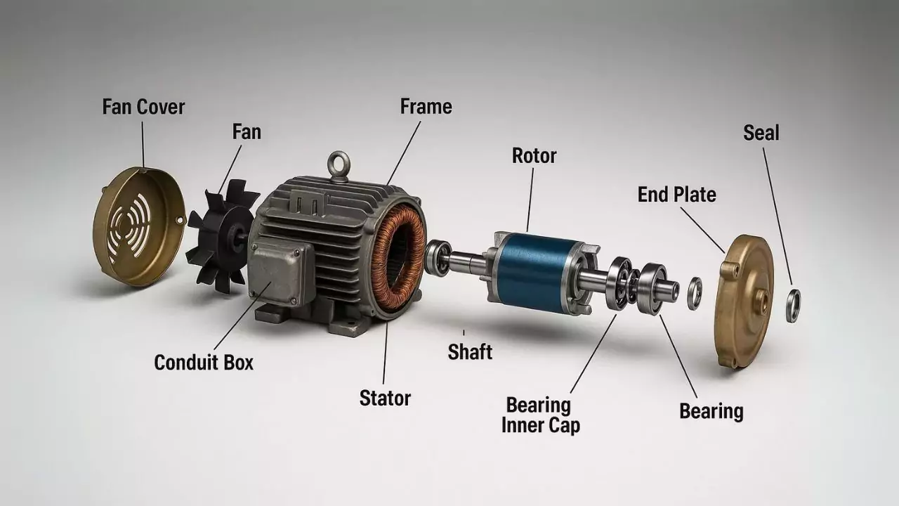
Three-phase motors, a category within A.C. motors, fall under the broader group of induction (asynchronous) motors. These motors are constructed with three primary elements: the stator, the rotor, and the housing.
The stator itself is made up of numerous thin steel laminations, each carefully stacked together. Wrapped around these laminations are coils of wire, arranged so that each coil aligns with one phase of the power supply. Each coil draws energy from its respective phase, which is essential for the motor’s function.
Moving to the rotor, you’ll find it consists of metal bars that are interconnected to form a closed loop, achieved through induction, not a direct connection to the power source. The rotor sits on the motor shaft, and it’s responsible for converting electrical input into mechanical output. Notably, it’s the only substantial part inside the motor that actually spins.
Encasing both the rotor and its shaft is the motor’s housing, which supports the shaft with a set of bearings. These bearings play a crucial role in minimizing friction as the rotor turns. The housing is fitted with end covers, which help secure the bearings, and often includes fans attached to the shaft itself.
As the shaft rotates, the fan pulls cooler air from outside the enclosure, directing it across both the rotor and stator. This airflow carries away heat that builds up in the coils due to electrical resistance.
For further cooling, you’ll typically find fins on the outside of the housing, helping to dissipate any remaining heat. The end covers or caps are also designed to allow access for making electrical connections required by the three-phase power supply.
Single Phase Motors
A single-phase motor is a type of electric rotary machine designed to convert electrical energy into mechanical motion, running on a standard single-phase power supply. These motors rely on two power lines: one live and one neutral.
Typically, single-phase motors deliver power outputs up to around 3 kW, though this can vary based on the input voltage. Because they operate using the same alternating voltage, their circuitry consists of two wires carrying alternating current—current that reverses direction thanks to the supply’s two poles.
In general, single-phase motors are relatively compact and intended for applications where high torque is not essential. They’re common in situations that call for modest mechanical power.
That said, there are models capable of producing more significant power, sometimes exceeding 10 horsepower, and running on voltages as high as 440V. It’s worth noting, however, that single-phase motors do not create a spinning magnetic field during operation; instead, they generate only an alternating magnetic field, which affects how they start and run.
One of the advantages of single-phase motors is their affordability and straightforward maintenance, making them a practical choice for a variety of settings. You’ll often encounter them in offices, retail spaces, homes, and other small-scale environments.
Their uses are widespread—everything from HVAC systems in residential and commercial buildings to household appliances, power tools like drills, air conditioning units, and even garage door openers rely on single-phase motors to function reliably.
Industrial Motors
Industrial electric motors are essential for transforming electrical energy into mechanical force, making them central to countless applications in manufacturing and beyond. These motors can generate either rotary or linear motion, depending on their design and intended use.
Broadly, industrial motors fall into two main categories: direct current (DC) and alternating current (AC) motors. In most industrial settings, AC motors are the preferred choice, largely because they are compatible with the standard power grid and are easily supplied by generators.
Every industrial motor, regardless of type, shares several key components. These include the rotor (sometimes referred to as the armature), the stator, the air gap between moving and stationary parts, the winding coils, and, in certain designs, a commutator.
The field is also quite diverse, with motor types such as DC synchronous, AC synchronous, and AC induction (also known as asynchronous) motors, each offering distinct advantages for different applications.
Servo Motors
A servo motor functions as either a rotary or linear actuator, providing highly accurate control over position, acceleration, and velocity. Essentially, a servo motor integrates a standard motor with a sensor, allowing it to constantly monitor and adjust its position as needed.
Operating a servo motor does require a more complex control system. These motors rely on specially designed controllers, which can be a bit more intricate compared to standard motor setups, but are necessary for achieving the precise movement that servo systems are known for.
It’s important to note that “servo motor” does not refer to a specific type of motor. Instead, the term simply means that the motor is being used in a closed-loop control system. You’ll often see servo motors in robotics, automated machinery, and other equipment where exact movements are crucial.
The type of motor used inside a servo setup isn’t always the main concern. Many applications favor simple brushed DC motors, largely because they are cost-effective and straightforward when it comes to gearing and design. However, not all servo motors are the same.
In certain industrial settings, small servo motors might be brushless and use electronic commutation, while larger applications typically employ AC induction motors, particularly when paired with variable frequency drives for precise speed control.
In cases where high performance is essential and space is at a premium, brushless AC motors with permanent magnets come into play. These are essentially a scaled-up version of brushless DC motors, tailored for environments where efficiency and compact design are priorities.
What are the applications and benefits of electric motors?
This section will address the applications, costs, and benefits of electric motors.
Applications of Electric Motors
Electric motors play a crucial role across a broad spectrum of devices and industrial applications. Their versatility can be seen in everyday items and heavy machinery alike, including fans, blowers, machine tools, turbines, pumps, power tools, compressors, alternators, rolling mills, movers, ships, and paper mills.
Beyond these, electric motors are also integral components in high-voltage AC heating systems, various cooling and ventilation equipment, automobiles, and numerous household appliances. Their widespread use underscores just how foundational electric motors are to both modern industry and daily life.
Benefits of Electric Motors
- Although electric motors typically involve lower upfront costs than fossil fuel engines, their horsepower ratings remain quite similar.
- Because electric motors contain fewer moving components, they generally offer greater durability and an extended operational life.
- When properly maintained, electric motors can function reliably for as many as 30,000 hours.
- Electric motors are also known for their high efficiency. They are often equipped with automated controls, enabling automatic start and stop functions without manual intervention.
- In terms of environmental impact, electric motors stand out as they operate without emitting harmful pollutants.
Drawbacks of Electric Motors
- Transporting large electric motors often presents significant challenges, particularly when it comes to organizing an appropriate current and voltage supply. These requirements can complicate both the movement and installation of such equipment.
- When electrical infrastructure is lacking, especially in remote areas, there are situations where substantial investments in line expansions become unavoidable just to ensure power reaches the site.
- If someone is operating a high-horsepower motor but only needs to use it for light or infrequent loads, the hourly operating costs can quickly add up, making the entire setup considerably expensive for the user.