A coupling is a mechanical component used to connect two shafts in order to transmit power efficiently from the driving shaft to the driven shaft.
In addition to this primary function, it also compensates for slight misalignments, mounting errors, and other mechanical inconsistencies between the two shafts.
In the field of mechanical engineering, the term coupling typically refers to any device that joins two rotating shafts together. Depending on the context, it may also be referred to as a shaft coupling or simply a joint.
Now, let’s take a closer look at what couplings are, how they work, and explore the different types that are commonly used in industry.
What is a Coupling?
A coupling is a mechanical component designed to connect two shafts at their ends, enabling the transfer of power between them. While the fundamental role of a coupling is to link two rotating pieces of equipment, it also accommodates a certain level of misalignment or axial movement or sometimes both between the connected shafts.
Broadly speaking, couplings can be understood as devices that join the ends of adjacent mechanical parts or components. Under normal operating conditions, most couplings are not intended to allow shaft disconnection.
However, some specialized versions, such as torque-limiting couplings, are built to slip or disengage automatically when torque levels exceed a defined threshold, thereby protecting the system.
It’s worth noting that choosing the right coupling, along with proper installation and routine maintenance, can significantly cut down both the time and cost associated with equipment upkeep.
This makes couplings not just functional connectors, but also strategic components in overall machinery efficiency.
The role of a coupling (shaft fitting)
- Transmit power
- Absorb misalignment
- Absorb vibrations to protect surrounding products
- Do not transfer the heat of the motor, etc., to the driven side.

What is Shaft Coupling?
A shaft coupling is a mechanical device used to connect a driving shaft to a driven shaft typically in motors or other rotating machinery to facilitate the transmission of power.
Its main role is to enable power transfer while accommodating a certain degree of misalignment between connected components.
One of the key advantages of shaft couplings is the mechanical flexibility they introduce into a system. This flexibility allows the shafts to operate even when they’re not perfectly aligned, helping to ease the load on bearings and reducing the likelihood of vibration, premature wear, or other mechanical issues that misalignment might cause.
Among the various types, flexible shaft couplings are particularly effective. They not only transmit torque between components but also compensate for angular, parallel, and axial misalignments.
When installed properly, these couplings can dampen vibrations, lower operational noise, and protect the integrity of the connected shafts and other drive elements.
Shaft couplings are widely used in systems where rotational power or torque must be transferred common examples include motor-to-pump setups, compressors, and generators.
Their application ranges from compact types designed for factory automation (FA) environments to larger cast versions meant for heavy-duty uses, such as in wind turbines or hydraulic power systems.
Types Of Shaft Coupling
Different types of shaft Couplings are:
- Rigid Coupling: They are used to connect two perfectly aligned shafts.
- Flexible Coupling: They are used to connect two shafts having lateral and angular misalignment.
- Fluid Coupling or Hydraulic Coupling: They transmit power from one shaft to another shaft, acceleration, and deceleration of hydraulic fluid.
MORE: What is Fluid Coupling?
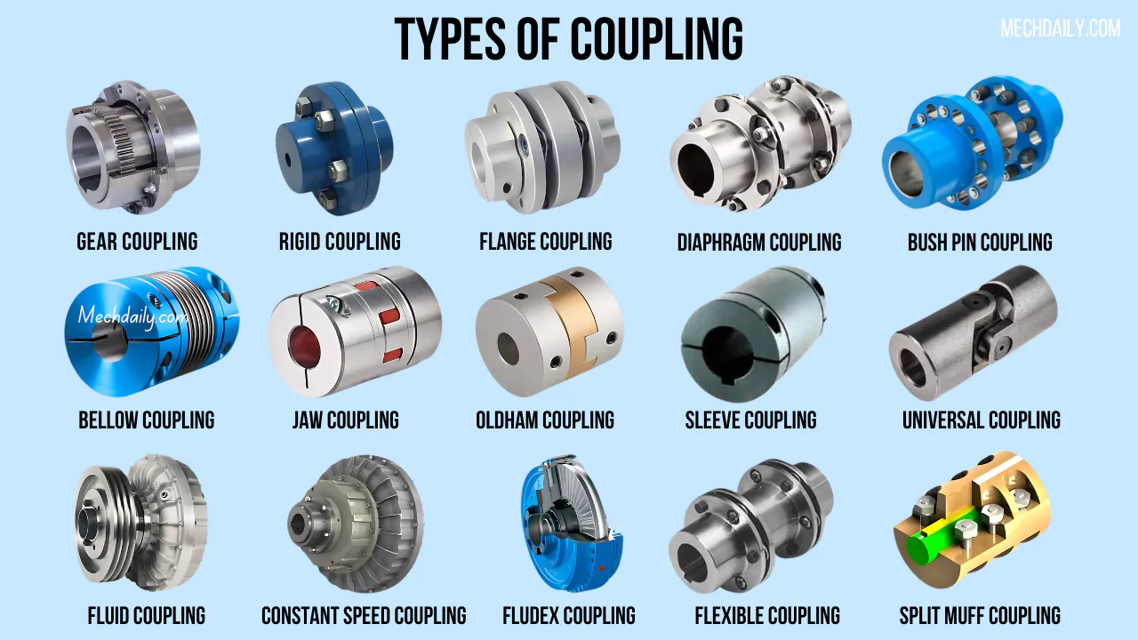
Types of Coupling
The following types of couplings and how they work:
- Rigid coupling
- Flexible coupling
- Sleeve or muff coupling
- Split muff coupling
- Flange coupling
- Gear coupling
- Universal joint (Hooke’s joint)
- Oldham coupling
- Diaphragm coupling
- Jaw coupling
- Beam coupling
- Fluid coupling
- Disc coupling
- Bushed Coupling
- Grid Couplings
- Roller Chain Coupling
- Tyre Couplings
- Bellows Coupling
#1. Rigid coupling.
Rigid couplings—often referred to as sleeve or muff couplings have traditionally been simple, cost-effective components, and in many cases, even fabricated in-house for basic shaft-to-shaft connections. These couplings are specifically designed to link two shafts in a way that eliminates any relative motion between them.
Because of their construction, rigid couplings are best suited for situations where precise shaft alignment can be achieved and maintained.
When shafts are misaligned either radially or axially rigid couplings don’t offer much tolerance. This misalignment can introduce significant stress into the system, which may eventually cause premature wear or failure.
True to their name, rigid couplings provide little to no flexibility once installed. Engineers typically choose them in systems where accurate shaft alignment is not just preferred but critical.
The term “rigid coupling” itself is quite broad, encompassing a few different types of mechanical connectors that serve this purpose. Common examples include sleeve couplings, compression couplings, and flange couplings—all of which are designed to minimize shaft movement.
When two equipment shafts are connected using a rigid coupling, the assembly essentially functions as a single, continuous shaft. This characteristic makes them especially useful in vertical applications, such as vertical pump assemblies, where maintaining shaft integrity is vital.
Rigid couplings also play a key role in high-torque applications. For example, large turbine systems increasingly rely on rigid couplings particularly between turbine cylinders because flexible couplings cannot withstand the required torque loads. Using rigid couplings in these setups ensures the turbine shaft operates as a unified, uninterrupted rotor.
#2. Flexible coupling.
Flexible couplings serve a vital role in mechanical systems: they transmit torque between two rotating components while accommodating a small degree of misalignment. This misalignment is typically measured in thousandths of an inch seemingly minor, but quite significant in precision applications.
By definition, a flexible coupling allows a certain amount of relative motion between connected shafts and also helps dampen vibrations. If machinery were perfectly aligned at all times and remained completely static during operation, the need for such couplings would vanish.
But real-world conditions rarely offer that level of perfection. Machines shift, vibrate, and undergo minor positional changes due to thermal expansion, loads, or settling, making flexible couplings not just useful but necessary.
Take CNC lathes as an example. These machines demand both high accuracy and high speed for precision machining tasks.
A rigid connection between shafts would amplify even the slightest misalignment or vibration, degrading performance. Flexible couplings, on the other hand, compensate for these inconsistencies, helping maintain both speed and precision.
In addition to improving performance, these couplings extend the lifespan of equipment by minimizing the mechanical stress caused by unavoidable imperfections. They’re also appreciated for their straightforward installation and impressive durability over time.
It’s worth noting that “flexible coupling” is a broad category encompassing a variety of designs. In fact, most couplings used in modern systems fall under this classification.
Common examples include gear couplings, universal joints, and Oldham couplings—each with its own set of advantages tailored to specific engineering needs.
#3. Sleeve or Muff Coupling.
A muff coupling, often referred to as a sleeve or box coupling, is one of the simplest and most straightforward forms of rigid shaft couplings. Structurally, it comprises just two main components: a cylindrical sleeve (or hollow pipe) and a sunk key.
The sleeve is slid over the aligned ends of two shafts, and the key fits into matching keyways cut into both the shaft and the inner bore of the sleeve. This setup ensures torque transmission between the shafts.
The bore of the sleeve is machined to match the shaft diameter with a close fit, allowing for proper alignment and torque transfer. Depending on the application, a keyway is carefully cut inside the sleeve’s bore. This keyway, along with the key itself, plays a crucial role in transmitting torque from the driving shaft to the driven shaft.
To secure the sleeve firmly in place, it typically includes two threaded holes. These allow for the insertion of set screws or bolts that help lock the coupling on the shaft, preventing any axial movement during operation.
In practice, sleeve couplings especially in their box form—connect the ends of two shafts by positioning them end-to-end within the sleeve.
The shafts are held tightly together using a gib head sunk key, which fits into the shared keyway and locks everything into one solid unit. The entire assembly is compact and reliable, making it a preferred choice in many straightforward mechanical applications.
Sleeve couplings are best suited for situations where light to medium torque needs to be transferred between shafts. They’re favored for their simplicity, cost-effectiveness, and ease of installation.
Since there are no complex components involved, maintenance is minimal, and alignment is relatively simple as long as the shafts are accurately positioned during assembly.
#4. Split Muff coupling.
In a split muff coupling also known as a compression or clamp coupling the sleeve is not a single, solid piece but is instead divided into two separate halves. These halves are semi-cylindrical in form and are designed to fit snugly over the shaft.
Each muff half includes threaded holes, which allow the two shafts to be securely fastened together using steel bolts or studs.
This type of coupling falls under the category of rigid couplings. Its construction typically involves two cast iron halves that form the sleeve. During assembly, one half is positioned beneath the shafts while the other is placed on top. The two halves are then tightly clamped using mild steel bolts or studs, along with nuts, to ensure a firm connection.
Depending on the application, the number of bolts used can vary commonly four or eight but they are always arranged in multiples of four. These bolts are inserted into recesses specifically designed in the sleeve halves to maintain a flush and secure fit.
One of the key practical benefits of a split muff coupling is that it allows for assembly and disassembly without requiring any alteration to the position of the shafts.
Because of this convenience, and due to its solid construction, it is particularly suitable for applications involving heavy-duty loads and moderate operating speeds.
#5. Flange Coupling.
A flange coupling is a type of mechanical connector commonly used to join two rotating shafts in machinery or piping systems. At its core, it consists of two flanges circular discs—each attached to the end of a shaft. These flanges are brought together and tightly secured using multiple bolts and nuts, forming a strong and stable connection.
One flange is fixed to each shaft, and when bolted together, they transmit torque from one shaft to the other. This setup ensures alignment and continuity in the rotational motion, making flange couplings essential in systems where shafts need to work in perfect unison.
Structurally, this coupling is designed to create a flush, sealed union between two tube or pipe ends. The system typically features a keyed component that allows the flanged end of one pipe to securely fit into place, matching up with the flanged end of the opposing pipe. This design helps form a tight and aligned connection between the two sections.
Each flange may have a male or female interface, which allows them to lock together accurately without causing friction or obstruction in the material flow—something particularly important when working with liquids, gases, or other media.
This male-female arrangement also plays a big role in maintaining a secure and shift-resistant bond, which is crucial for maintaining both mechanical integrity and safety in pressurized systems.
Flange couplings are especially useful in high-pressure piping networks or in situations where the materials being transported are hazardous or corrosive. Because of this, the coupling must be extremely secure.
The bolts used are often high-thread count fasteners, made from tempered steel or specialized alloys. This material choice ensures they can handle the stress, maintain a tight seal, and resist wear over time.
Depending on the system’s size and pressure requirements, flange couplings might use four, six, or even up to twelve bolts to ensure the joint stays intact under demanding conditions. When properly installed, they offer both mechanical strength and leak resistance—making them a trusted choice in many industrial applications.
#6. Gear Coupling.
Gear couplings are mechanical components specifically engineered to transfer torque between two shafts that are not aligned in a straight line. Typically, they are made up of two flexible joints—each mounted on one of the shafts—which are linked together by a spindle or an intermediate shaft.
In practical applications, such as hoist mechanisms, gear couplings are often used to connect a drive motor to a gearbox. In some setups, they may also link the gearbox directly to smaller wire rope drums through a flanged half-coupling.
From a design standpoint, torque transmission in gear couplings occurs through hubs equipped with crowned gear teeth. These teeth remain in continuous mesh with the straight-cut teeth on the coupling sleeves. This particular configuration enables the coupling to handle high torque loads efficiently while keeping the overall size compact.
Additionally, gear couplings are capable of operating at high rotational speeds. They are built to match the AGMA (American Gear Manufacturers Association) bolting pattern and are designed to accommodate angular, radial, and axial misalignments between the connected shafts.
#7. Oldham Coupling.
Oldham couplings are made up of three main components: two outer hubs—typically crafted from lightweight aluminum or corrosion-resistant stainless steel—and a central disk.
This central piece connects the two hubs through a tongue-and-groove interface, with each hub featuring tenons that fit snugly into corresponding slots on the disk. Thanks to this slight press-fit, the coupling delivers zero backlash during operation, which is a critical feature in many precision-driven systems.
You’ll often find Oldham couplings in servo-driven applications where accurate motion control and minimal inertia are priorities. Their balanced design helps maintain system stability, especially in setups where smooth and repeatable movement is essential.
What makes the Oldham coupling stand out among flexible couplings is its ability to eliminate backlash—something that’s increasingly turning it into a preferred alternative to traditional straight jaw couplings.
Structurally, it’s made up of three disks: the two outer ones connect to either side of a shaft or drive system, while the middle one—usually made of a durable plastic—sits in between and links them through an offset groove system.
One side’s tongue-and-groove pattern is oriented 90 degrees from the other, which is key to how torque gets transmitted.
When the coupling is in motion, the center disk slides back and forth across the hub tenons, which are offset perpendicularly. This sliding action not only transfers torque but also compensates for misalignments—particularly parallel misalignment. While it can tolerate some angular and axial offset, that’s not its main strength.
Another practical benefit of the Oldham coupling is its compact footprint, which makes it a good fit for tight spaces. The plastic center disk also offers electrical isolation—an advantage in systems where electrical continuity between shafts could be problematic.
On top of that, the design acts a bit like a mechanical fuse. If the torque in the system spikes beyond safe limits, the central disk is designed to shear first, effectively halting torque transmission and protecting more expensive components from damage.
#8. Universal Coupling.
A universal coupling, also commonly referred to as a Hooke’s joint or hook coupling, is typically used to connect two shafts whose axes intersect at a slight angle.
While it might seem like the angular displacement between the shafts remains uniform, in practical operation, that’s rarely the case. When torque or momentum is transferred from one shaft to another, there’s usually a noticeable variation in angular velocity.
One of the most common uses of a universal coupling is in automotive applications—specifically, in transmitting power from the gearbox to the differential or rear axle.
In these setups, the coupling is generally employed in pairs: one end is connected to the gearbox, and the other to the differential, with both ends joined through the propeller shaft.
Beyond automotive systems, hook couplings also find use in other mechanical setups. For instance, they are employed to deliver rotary motion to multiple spindles in various drilling machines.
Additionally, in milling machines, the universal joint often serves as a flexible joint in the knee mechanism, allowing movement and torque transfer at varying angles.
#9. Diaphragm Coupling.
A diaphragm coupling is a type of flexible coupling that uses one or more thin metallic membranes to transmit torque. These membranes are typically connected at the outer diameter of a drive flange, and they transfer torque radially through the diaphragm to an attachment point at the inner diameter. This setup allows for both flexibility and precise torque transmission under varying load conditions.
In addition to diaphragm couplings, another common variant of metallic membrane coupling is the disk coupling. While both function on a similar principle, diaphragm couplings specifically rely on a single plate or a stacked series of diaphragms to act as the flexible element.
The torque transmission process in a diaphragm coupling begins at the outer edge of the flexible plate. From there, the torque is passed inward through the diaphragm, across the central spool or spacer element, and then outward again—from the inner to the outer diameter—on the opposite side.
This design not only provides mechanical flexibility but also helps accommodate minor misalignments between connected shafts.
- Allows for angular, parallel, and high axial misalignments
- High torque, used in high-speed applications
#10. Jaw Coupling.
A jaw coupling is a widely used, general-purpose component in power transmission systems, and it’s also commonly found in motion control setups, such as those involving servo motors.
Its main role is to transfer torque between two connected shafts. But beyond that, it plays an important part in reducing system vibrations and compensating for minor misalignments between shafts—helping to safeguard surrounding components from potential wear or failure.
Structurally, a jaw coupling consists of three main parts: two metallic hubs and a flexible elastomer insert, which is often called a “spider.” These components are assembled in a press-fit configuration, where the jaws of each hub interlock with the lobes of the spider in an alternating pattern.
The way torque is transmitted in this setup is through the elastomer element, which compresses as force is applied. This compressive interaction is what allows the coupling to deliver power while also absorbing shocks and slight deviations in alignment.
- Flex element is commonly made of NBR, polyurethane, Hytrel, or Bronze
- Accommodates misalignment
- Transmits torque
- Used for torsional dampening (vibration)
- Low torque, general-purpose applications
#11. Beam coupling.
A beam coupling—often called a helical coupling—is a type of flexible coupling used to transmit torque between two shafts.
What makes it especially useful is its ability to handle more than just rotation: it can compensate for angular misalignment, slight parallel offsets, and even axial movement between the shafts. That’s something rigid couplings simply can’t do.
The design is quite clever. It’s made from a single solid piece of material, and flexibility is achieved by cutting a helical groove along its length. This spiral cut gives the coupling just enough give to flex while still maintaining the strength needed to transfer torque reliably.
What sets beam couplings apart from other types—besides their flexibility—is that one-piece construction. Because there are no joints or assembled components, there’s no room for backlash, which can be a problem with couplings made from multiple parts. This makes them a popular choice in applications where precision matters.
You’ll find beam couplings made from several different materials, including titanium and acetal. But the most commonly used ones are aluminum and stainless steel. Each has its trade-offs.
Aluminum beam couplings are lightweight, which makes them a great fit for setups that require quick response and low inertia. Stainless steel couplings, while heavier, offer superior strength and torsional stiffness. That added mass, however, means they’re not as responsive as their aluminum counterparts.
#12. Fluid coupling.
A fluid coupling is a mechanical device designed to transmit torque between two shafts using hydraulic fluid. It serves as a means of power transmission without a direct mechanical connection, relying instead on the movement of fluid to transfer energy.
The assembly typically includes two main components: an impeller, which is attached to the driving shaft, and a runner, which is connected to the driven shaft. Both are enclosed within a casing, often referred to as the housing or shell.
As the driving shaft begins to rotate, the impeller also spins, causing the fluid inside the housing to circulate. This fluid, now in motion, impinges upon the blades of the runner.
The interaction transfers mechanical energy from the fluid to the runner, which in turn drives the output shaft. By the time the fluid exits the runner blades, its velocity has significantly decreased, completing the energy transfer cycle.
Fluid couplings are widely used in applications that demand smooth torque transmission and protection against shock loads. Common uses include automotive transmissions, marine propulsion systems, locomotives, and various industrial machines that operate under continuous or cyclic loading conditions.
#13. Disc Coupling.
A disc coupling serves the primary function of transmitting torque from a driving shaft to a driven one by means of a tangential force applied along a shared bolt circle. This transmission is achieved through a carefully arranged pack of thin stainless steel discs, which connect bolts on either side.
What sets this coupling apart is its ability to manage misalignment between shafts—not by adding extra mechanical parts, but by allowing slight deformation in the disc material itself.
This built-in flexibility enables the coupling to accommodate angular, parallel, or axial misalignments without sacrificing performance.
Engineered for high-performance motion control systems, disc couplings provide a robust connection between two shafts while maintaining the ability to flex where needed.
Even under high torque conditions, they remain torsionally rigid, meaning they resist twisting—but they still have enough give to handle small misalignments.
Many of these couplings are rated for rotational speeds up to 10,000 revolutions per minute, making them a reliable choice for demanding, high-speed applications.
Disc couplings generally come in two styles:
- Single-disc couplings feature two hubs—usually machined from aluminum, though stainless steel is sometimes used—and a single, flat stainless steel disc spring that joins them.
- Double-disc couplings, on the other hand, include a center spacer positioned between two disc springs. This design also has two hubs, and the spacer may be made of the same material as the hubs or, in some cases, from insulating acetal. The latter option is particularly useful in applications where electrical isolation is required.
Because they are both torsionally stiff and flexible, disc couplings offer a solid solution for systems that demand both precision and speed. That said, they aren’t indestructible.
One trade-off is their delicacy compared to more rugged coupling types—they can be damaged if misused or subjected to loads outside their design limits.sused. Special care should be taken to ensure that misalignment is within the ratings of the coupling.
#14. Bushed Coupling.
Bush couplings play a crucial role as flexible connectors, especially in setups that demand reliable power transmission even under tough working conditions.
At the core of their design, a bush coupling includes two hubs—often made from different materials—that are joined using pins. These pins are fitted with rubber bushes, allowing the coupling to absorb shocks and accommodate slight misalignments between shafts.
Because of their dependable performance and flexibility, bush couplings are commonly found in hoisting machinery and similar heavy-duty applications.
The pins, often referred to as coupling bolts, are typically covered with rubber or leather bushes. An important detail in their structure is the slight variation between the two halves of the coupling.
A 5 mm gap is intentionally maintained between their faces. This space ensures that there’s no rigid metal-to-metal connection; instead, the power is transmitted through the compression of the rubber or leather bushes.
#15. Bellow Couplings.
Bellows couplings fall under the category of flexible couplings and are characterized by their two end pieces—commonly known as hubs—attached to a precisely crafted corrugated tube, which acts as the main body of the coupling.
What sets bellows couplings apart is their remarkable torsional rigidity. This allows them to transmit torque, angular position, and rotational speed with a high degree of accuracy.
Despite their rigidity, they offer just enough flexibility at the corrugated section to compensate for minor misalignments—whether axial, angular, or parallel—between connected shafts or components.
These couplings are most often made from stainless steel, using a process called hydroforming (though sometimes welding is used instead). It starts with a flat sheet of metal—typically stainless steel—which is shaped into a tube.
This tube is then internally pressurized against a ribbed die, giving it its distinctive corrugated form. Once the bellows shape is formed, hubs are either welded or bonded onto each end to complete the coupling.
How Does a Coupling Work?
Couplings serve a critical function in mechanical systems by firmly connecting two shafts, enabling efficient transfer of power from one to the other.
In addition to this primary role, couplings help manage the physical stress that comes with operation absorbing shocks, vibrations, and heat generated by the driving shaft.
This not only ensures smoother torque transmission but also protects nearby components from potential wear or damage.
When a rigid coupling is installed, it effectively makes two independent shafts behave as a single unit. Thanks to their high torsional stiffness, these couplings prevent any relative movement between the connected shafts.
By eliminating that movement, the system achieves optimal torque transfer, improving both performance and reliability.
Use of coupling
Shaft couplings are used in machinery for many purposes, the most common of which are the following:
- For connection to shafts of units manufactured separately as a motor and generator and provide for repair or disconnection for option.
- To provide shaft misalignment or to introduce mechanical flexibility.
- To reduce the transmission of shock loads from one shaft to another.
- To introduce protection against overload.
- It should not have any projecting parts.
The Purpose of Couplings
Shaft couplings play a crucial role in many mechanical setups, often serving more than one function depending on the complexity of the application. In more advanced systems, it’s common for a single coupling to integrate multiple performance features. Here’s a closer look at the key roles these components typically fulfill:
1. Power and Torque Transmission
At its core, the most fundamental purpose of a shaft coupling is to transfer power from a driving shaft to a driven shaft. This is typical in systems like electric motors connected to pumps or compressors. The coupling ensures a smooth and efficient transfer of torque between the two components.
2. Shock and Vibration Absorption
Another important role of a coupling is to absorb shocks or vibrations generated during operation. By dampening these forces before they reach the driven element, the coupling helps minimize wear and tear, ultimately extending the lifespan of the machinery.
3. Misalignment Compensation
Shafts are rarely perfectly aligned—whether due to installation errors or gradual shifts during operation. Most modern couplings are designed to handle a certain amount of misalignment, whether it’s axial, angular, or parallel. This flexibility reduces the risk of mechanical strain or failure.
4. Thermal Isolation
In setups where the driving component (like a motor) tends to heat up during use, couplings can serve as a barrier that limits the transfer of heat to the driven side. This protects temperature-sensitive components downstream from potential thermal damage.
5. Overload Protection
Some couplings are specifically engineered to protect systems from torque overloads. These are often referred to as overload safety mechanical couplings. When an overload is detected, they either slip or disconnect entirely, preventing damage to delicate or high-precision equipment.
Requirements of a good coupling
A good shaft coupling should have the following requirements:
- It should be simple to connect or disconnect.
- It must transmit full power from one shaft to another shaft without damage.
- It should hold the shaft in the correct alignment.
- It should decrease the transmission of shock loads from one shaft to another.
- It should not have any projecting parts.
Parameters for Choosing Couplings
Shaft couplings play a crucial role in both motion control and power transmission systems. When chosen and applied appropriately, they can offer significant benefits while also addressing common challenges related to system assembly and operating conditions.
To ensure the correct coupling is selected, engineers and system designers must take several key factors into account. Being mindful of these considerations can not only help prevent coupling failures but also enhance overall system performance. These important factors include:
Torque Requirements
Torque ratings are one of the main criteria used by manufacturers to classify different types of shaft couplings. The level of torque a coupling must handle largely depends on the nature of the application—whether it’s for motion control or power transmission.
Typically, motion control applications involve lower torque loads, whereas power transmission tasks demand higher torque capacity. Understanding the torque expectations for the system allows designers to narrow down the suitable coupling options.
Alignment Tolerances
Not all applications require the same alignment conditions, and likewise, not all couplings are designed to accommodate every type of misalignment. Some couplings can manage angular misalignment, others axial, and a few are built to handle multiple misalignment types simultaneously.
Manufacturers usually specify the allowable limits for each type of misalignment in their product documentation. By matching these specifications to the application’s alignment characteristics, designers can further refine their selection.
Speed Limitations (RPM)
Each coupling is designed with a specific maximum rotational speed, often expressed in revolutions per minute (RPM). These limits are always provided in product data and should not be overlooked—particularly in high-speed applications.
Standard couplings may not be suitable for such conditions without modifications. For high-RPM environments, dynamic and static balancing is essential to maintain smooth operation, minimize vibration, and reduce noise.
These performance characteristics are typically achieved through precision manufacturing and balanced component distribution. Factoring in the system’s expected RPM early in the selection process helps avoid performance issues down the line.
Lubrication Considerations
In some operating environments, frequent relubrication may not be feasible due to accessibility or service constraints.
While certain shaft couplings rely on periodic lubrication for optimal performance, others are engineered to operate maintenance-free for their entire service life. Choosing between these types depends on the maintenance capabilities and demands of the system where the coupling will be used.
Coupling maintenance and failure
Coupling maintenance requires a regularly scheduled inspection of each coupling. It consists of:
- Conduct regular visual inspections to identify any obvious defects, misalignments, or damage that could affect coupling performance.
- Monitor for signs of wear and fatigue, such as surface cracks, corrosion, or deformation. Early detection can help prevent unexpected failures during operation.
- Clean the couplings on a consistent basis to remove dirt, debris, and buildup that may interfere with their function or lead to premature wear.
- If the coupling is of a lubricated type, check the lubricant condition and replace it as needed. In most cases, this should be done at least once a year; however, in harsher environments or under more demanding operating conditions, more frequent maintenance may be necessary.
- Keep a detailed record of all maintenance activities, including the type of service performed and the date. Proper documentation supports long-term equipment reliability and simplifies future inspections.
Even with proper maintenance, however, couplings can fail. Underlying reasons for failure, other than maintenance, include:
- Improper installation
- Poor coupling selection
- Operation beyond design capabilities.
The only way to improve coupling life is to understand what caused the failure and to correct it prior to installing a new coupling. Some external signs that indicate potential coupling failure include:
- Abnormal noise, such as screeching, squealing, or chattering
- Excessive vibration or wobble
- Failed seals are indicated by lubricant leakage or contamination.
FAQs
What is a coupling in engineering?
Couplings are defined as mechanical components used to connect two shafts. They serve primarily to transmit energy from the drive side to the driven side of a rotary system, and secondary functions include compensating for misalignment or reducing vibration.
What is a coupling on a shaft?
A shaft coupling is a mechanical component that connects the drive shaft and driven shaft of a motor, etc., in order to transmit power. Shaft couplings introduce mechanical flexibility, providing tolerance for shaft misalignment.
What is coupling joints?
The primary purpose of couplings is to join two pieces of rotating equipment while permitting some degree of misalignment or end movement or both. In a more general context, a coupling can also be a mechanical device that serves to connect the ends of adjacent parts or objects.
What is coupling in construction?
Couplings are critical components in rotary motion systems such as driveshafts, generators, and motors. In these applications, couplings join two shafts together to stabilize them against shock load and overload. The joint between shafts can be temporary or permanent.
What are the two most common types of couplings?
There are two main types of couplings: rigid couplings, which connect two shafts with a solid and high-precision hold, and flexible couplings, which can be used to connect slightly misaligned shafts but which can’t provide the same level of torque transfer.