In most engineered products, functionality depends heavily on how well different components fit or slide into one another. Whether it’s parts that lock tightly or those that move freely, the way these pieces come together plays a critical role in how the product performs.
In this guide, we’ll break down the different types of fits used in mechanical engineering—what they are, where they’re used, and how to decide which one is right during the design phase of your project. Understanding these fits isn’t just about following standards; it’s about making smart design decisions that can improve reliability, performance, and even manufacturability.
So, if you’re in the process of designing a product or just brushing up on the basics, you’re in the right place. Let’s get into it.
What Is An Engineering Fit?
When designing a part or an assembly, especially in the context of geometric dimensioning and tolerancing, the concept of engineering fits plays a crucial role. At its core, a fit refers to the clearance or sometimes the lack thereof between two mating components.
This clearance determines how those parts interact: whether they’re meant to rotate or slide freely, align precisely, or remain tightly joined either temporarily or permanently.
While fits are commonly illustrated using the “shaft and hole” model, it’s important to note that they’re not confined to circular geometries. The principle applies to a wide variety of mating parts in mechanical systems.
Internationally, the ISO (International Organization for Standardization) system is the most widely adopted framework for defining engineering fits. However, in North America, the ANSI (American National Standards Institute) system is still frequently used.
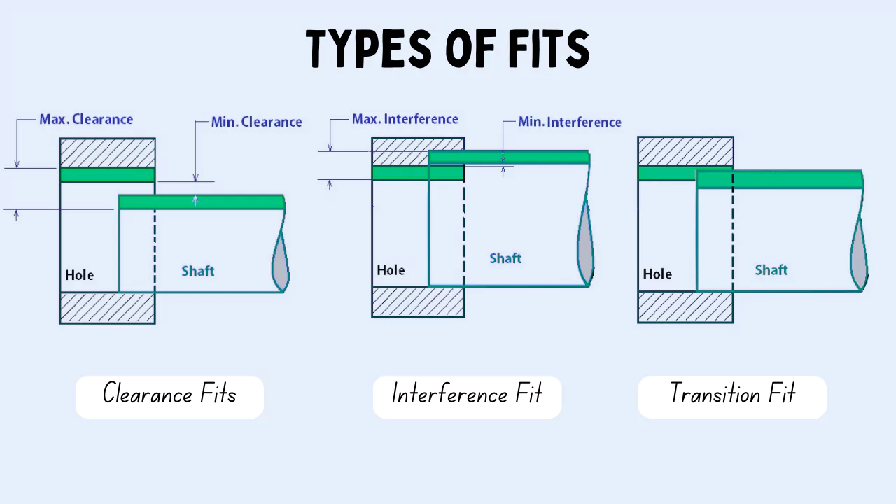
Both systems classify fits into three main types: clearance fits, transition (or location) fits, and interference fits. Each category comes with its own set of codes that define the permissible size variations for holes and shafts, and the specific pairing of these codes dictates the resulting type of fit.
Choosing the right type of fit isn’t a random decisionit’s something that’s typically determined early in the design process. Engineers consider how the parts need to behave in operation:
- Do they need to move freely?
- Do they need to stay precisely aligned?
- Should they come apart easily, or are they meant to resist separation?
Alongside these functional concerns, cost is a major consideration. Tighter, more precise fits demand higher manufacturing accuracy, which in turn can significantly raise production and assembly costs.
To achieve the tolerances needed for a specific fit, a variety of manufacturing processes may be employed. Broader tolerances can often be met using casting, forging, or drilling.
When higher precision is necessary, methods such as reaming, milling, and turning come into play. At the most demanding end of the spectrum where the tightest tolerances are required—techniques like lapping and honing are used.
Maximum and minimum clearance
When discussing mechanical fits, maximum clearance refers to the largest possible gap between the orifice (or hole) and the shaft. This occurs when the orifice is at its largest allowable diameter and the shaft is at its smallest. Mathematically, it’s expressed as:
Maximum clearance = largest orifice diameter – smallest shaft diameter
On the flip side, minimum clearance represents the tightest possible condition. It’s calculated by taking the smallest allowable diameter of the orifice and subtracting the largest possible diameter of the shaft:
Minimum clearance = smallest orifice diameter – largest shaft diameter
In the case of loose or sliding fits, the maximum clearance is always greater than zero, ensuring some amount of play between the parts. However, with a tight fit, it’s a different story—both the maximum and minimum clearances end up being negative, which means the parts interfere with each other even at their most permissive tolerances.
Types Of Fit
There are three types of fit commonly referenced in manufacturing and mechanical engineering.
#1. Interference Fit.
In mechanical engineering, an interference fit sometimes referred to as a friction fit is a fastening method where components are joined together with intentional tightness.
The core idea behind this fit lies in the high frictional force that holds the mating parts securely, thanks to a condition known as negative clearance. Essentially, the parts are slightly larger or smaller relative to each other, which causes them to press firmly together when assembled.
To put it simply, interference fits rely on the deformation of the parts at the contact surfaces. A common example would be a shaft and a hole: in this case, the hole is made slightly smaller than the shaft.
When assembly happens often using a hydraulic press or even with hammering the shaft is pushed into the hole, causing both surfaces to slightly deform and lock together under pressure. This tight engagement is the reason the fit is sometimes also described as a press fit.
Another widely used approach to achieve interference fits is shrink fitting. Here’s how it works: one of the two parts (either the inner or outer component) is temporarily altered in size using temperature.
You might heat up a ring to make it expand, or chill a shaft with liquid nitrogen so it shrinks. This temporary expansion or contraction changes the negative clearance into a positive one, making it easier to assemble the parts.
Once everything returns to room temperature, the part either shrinks or expands back, locking into place and creating the interference fit.
As for the degree of tightness, the typical clearance range in these fits can be anywhere between -0.001 mm and -0.042 mm, depending on the specific application and tolerance requirements.
With the basics covered, let’s move on to the different types of interference fits and how they’re used across various engineering applications:
- Press Fit: A lighter variant of press fitting with minimal negative clearance for medium-strength joints.
- Driving Fit: Medium interference joint that can carry loads and requires cold/hot pressing and force to assemble.
- Forced Fit: Forced fits are the strongest type of engineering fit. They require cold/hot pressing and are almost always permanent. Their assembly warrants careful tolerancing and placement to avoid the breakage of parts.
#2. Clearance Fit.
A clearance fit is characterized by a positive allowance, meaning there is a small, intentional gap between the mating components. This slight space allows the parts to fit together without interference, and although it introduces a bit of “play” or looseness, it is typically minimal often so small that it’s not noticeable without precise measurement.
This minor play gives the components a limited degree of movement. Take, for instance, the relationship between a pin and a frame in a pivot joint: they are designed with a clearance fit, which allows each part to move independently while still remaining properly engaged and functional within the assembly.
In practical terms, the amount of clearance in such fits usually falls within a specific range typically from +0.025 mm to +0.089 mm. This range ensures both ease of assembly and reliable performance. Below is a brief overview of the various types of clearance fits:
- Loose Running Fit: In this type of fit, the clearance is set at the higher end of the recommended range. It allows the parts to rotate or slide freely, and there’s noticeable play between the components. This fit is typically used where precision isn’t critical, and unrestricted movement is needed.
- Free Running Fit: This fit is quite similar to the loose running type but is designed for components that operate at high speeds. It also offers enough space to accommodate thermal expansion. However, because of the significant clearance, the parts don’t stay precisely aligned so accuracy in positioning is relatively low.
- Close Running Fit: A step up in precision, close running fits provide better control over positioning while still allowing movement under high-speed and high-temperature conditions. The clearance is tighter than in the previous types, which helps maintain better alignment between parts.
- Sliding Fit: This is a more refined type of fit used when high accuracy is required. The clearance is kept very tight, just enough to permit motion in one direction—sliding—while restricting all other forms of movement. It’s commonly used in applications where guided, linear movement is essential.
- Location Fit: Location fits are designed for maximum precision when aligning or assembling mating parts. The clearance is minimal, and in most cases, lubrication is necessary to ensure smooth operation. This fit is ideal when the parts need to stay in a fixed position with minimal play.
#3. Transition Fit.
A transition fit serves as a middle ground between clearance and interference fits, offering a flexible solution depending on the specific engineering application. In this type of fit, the assembled parts may end up with either a slight clearance or a slight interference, based on their actual tolerances.
When a slight interference occurs similar to an interference fit it doesn’t generate high pressure or significant load-bearing capacity. Conversely, if there’s a small clearance akin to a clearance fit it still limits excessive looseness or free play between the parts.
This balance makes transition fits particularly effective in situations where precise alignment is essential. They’re often chosen in assembly processes that require components to be located accurately without subjecting them to high mechanical stress or deformation.
In terms of dimensional range, the typical mechanical interference or clearance for a transition fit lies between +0.023 mm and -0.018 mm. There are also two standard types of transition fits, which are commonly used based on the required performance.
- Similar Fit: This type of fit involves minimal clearance or interference it’s a very light engineering fit. Typically, it’s snug enough that it doesn’t just slide in on its own, but you can usually assemble it using a bit of force something like a light tap with a mallet is often enough to get the job done.
- Fixed Fit: A fixed fit is a step tighter compared to a similar fit. Here, the connection is firm enough that simple manual force won’t cut it you’d usually need a press to complete the assembly. It’s still not an extreme interference, but definitely more secure than the previous one.
How to Choose the Right Fits in Engineering
Selecting the appropriate type of fit for your project requires a careful consideration of several key factors. It’s essential to be mindful of the following aspects before making a decision:
Application
Choosing the right type of fit really comes down to understanding what your specific project needs. Different fits serve different functions, so it’s important to look at key factors like accuracy, tolerance levels, and the role the final product is expected to play.
When you match these technical details with the purpose your design is meant to serve, you’ll be in a much better position to determine which fit is the most suitable.
Budget
Before selecting the appropriate type of fit for your product, it’s important to start with a clear understanding of your budget. Tighter tolerance fits, while often necessary for certain applications, generally come with higher costs.
This means you’ll need to evaluate your choices thoughtfully. The goal is to choose a fit that provides the level of precision required for the part to function properly without unnecessarily driving up development expenses. Striking this balance is key to creating a product that is both reliable and cost-effective.
Tolerance
Understanding the concept of product tolerance is essential when selecting the appropriate type of fit for any component or assembly. It’s not just about knowing the standard definitions it’s about being precise with what you expect from the final product.
For instance, you need to clarify whether the parts are intended to rotate freely or fit together tightly without movement. That decision directly influences the kind of fit you should choose.
Another crucial factor to consider is tolerance slack. This refers to the total allowable variation whether maximum or minimum in a given measurement. It’s especially important to pay attention to how the tolerances of individual parts add up in an assembled product.
If those tolerances accumulate beyond acceptable limits, it could affect the performance or quality of the entire system. In cases where the overall tolerance stack-up is significant, the consequences can’t be ignored.
FAQs
What are 3 types of FITS?
There are three types of fit commonly referenced in manufacturing and mechanical engineering.
1. Clearance Fit. Clearance fits allow for loose mating, where free movement is important and a certain amount of play is desired.
2. Interference Fit. An interference fit will be much tighter than a clearance fit.
3. Transition Fit. A transition fit would fall between a clearance and interference fit.
What is a H7 fit?
For example, in H7/h6 (a commonly-used fit) H7 represents the tolerance range of the hole and h6 represents the tolerance range of the shaft. These codes can be used by machinists or engineers to quickly identify the upper and lower size limits for either the hole or shaft.
What is the difference between fit and FITS?
The past/past participle form of the verb fit is normally fit. The first sentence is in the past, so the “fit” has been used in the sentence as the past form, not the present form. If you want to form the sentence in the present, you can use fits as follows: I am wondering if it fits you.
What is a wringing fit?
Wringing fit: Wringing fit is used when the parts need to be replaced without any difficulty. A common example is the assembly of pulleys on a drive shaft and a driven shaft.
What are the classification FITS?
Both ISO and ANSI have standardised fits in three classes – clearance, transition and interference. Each class has a variety of options available for choosing the correct one for a specific application.