A draw die is a specialized tool that is used in the manufacturing sector to produce shapes with three-dimensional, hollow forms, such as those produced in deep-drawing processes.
Draw die manufacturing is an essential part of creating a broad range of everyday products: beverage cans, automotive exterior body parts, appliance casings, road and building materials, etc.

What is a Draw Die?
A draw die is a specialized tool used in the sheet metal forming process to shape flat sheet metal into complex, three-dimensional parts.
It is an important component of manufacturing, allowing the precise and repeatable forming and shaping of metal components that are used in everything from automotive, aerospace, and consumer products.
The drawing process allows the metal sheet to be stretched into the form of the die cavity by the use of a punch preventing the metal from tearing or wrinkling in the process.
What makes a draw die unique is that it controls the flow of material while forming. This is controlled by the built-in components of the punch, die cavity, and blank holder designed in accordance with the forming process.
These components provide pressure to deform and control the plate, properly shaping the final part while ensuring dimensional accuracy and structural integrity.
What is Drawing in Metalworking?
Metalworking “draw” is the process of pulling a flat sheet metal blank into a die cavity with a mechanical punch to achieve a desired contour.
The differentiating characteristic is that the material is not actually cut, but rather plastically deformed. Plastic deformation means that the material stretches without splitting. It can be compared to pulling dough over a mold. it conforms to the shape and remains intact.
This process is generally used for making shapes that are cylindrical, box-like, or contoured without seam lines. The sheet must be made out of a material that has enough ductility, so it can be stretched without ripping.
Basics of the Drawing Process
Deep drawing is a sheet metal forming process that utilizes a combination of both tensile and compressive stress to form parts. The basic steps of the process are:
- Blank Placement: To begin, a flat sheet metal blank, which can have a circular or rectangular shape will be placed over the die cavity.
- Blank Holding: A blank holder, also called a binder, descends and presses down at the edges of the blank to hold it against the die. The pressure applied with the blank holder helps to regulate the flow of material and avoids wrinkling occurring.
- Punch Descend: The punch, which is the male part of the die set, will now descend into the die cavity and push down on the blank in the center of the blank.
- Material Flow and Deformation: The punch will push down on the blank, thus the material in the flange area (that portion of the blank being held by the blank holder) will undergo a radial flow pattern and the material will also be subjected to a tangentially compressive stress. The punch exerts tensile stress on the material that is deformed under the punch. This combination of stress allows for a controlled material flow to be drawn as well as the metal to stretch, deform and take the shape of the punch and die.
- Part Formation: The punch continues to descend until the formed part is of the desired depth and shape.
- Ejection: After the drawing operation is complete, the punch is retracted and the formed part is ejected from the die.
In many instances, several deep drawing operations (called re-drawing) will occur using die/punch combinations that increasingly become smaller so that complex and/or very deep parts can be formed.
In certain cases, intermediate annealing may also be required to restore ductility to the material.
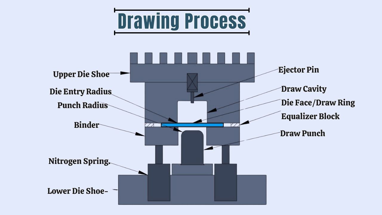
Components of a Draw Die
Most draw die sets come with some form of draw die set parts. These parts include the following:
- Punch: This is the male portion of the die that pushes the material into the cavity of the die. The shape of the punch is used to establish the inner contour of the part being drawn.
- Die (or die cavity): This is the female part of the die set that establishes the outer contour of the drawn part.
- Blank Holder (or Binder): This is a ring-shaped part that holds the blank against the die to prevent wrinkling of the blank material during the drawing process, and the blank holder force can be used to control the flow of the material into the die cavity.
- Pressure Pad/Ejector: This is a mechanism, normally located at the base of a die, that helps eject the formed part after the drawing operation is complete.
- Draw Beads: These are raised sections of the blank holder or die that create resistance to flow of the material into the die cavity to control the flow of material.
- Die Plate: The base plate that contents of the die are built into.
Types of Drawing Dies
Drawing dies, in terms of broad application, are classified in the same way regardless of the complexity and drawing operation:
#1. Wire Drawing Dies.
Wire Drawing Dies are probably the most common drawing dies and are used in the production of wires of various diameters to service a broad range of industries, such as electronics and manufacturing.
Natural Diamond Dies (ND Dies):
Natural diamond dies (ND Dies) are made from single natural diamonds, and possess outstanding hardness and wear resistant properties.
ND dies are typically used to draw very fine wire, particularly in applications where high-precision and superior surface finish are required, such as in the making of high-precision wires used in electronic devices, radar and aerospace applications.
Applications: Ultrafine wires made with copper, stainless steel, tungsten, molybdenum and other types of precious metals.
Polycrystalline Diamond Dies (PCD Dies):
Polycrystalline Diamond Dies (PCD) are made by sintering diamond powder at ultra-high temperature and pressure to obtain exceptional wear resistance and thermal conductivity.
PCD dies are more rigid than ND dies, and can go much larger than ND dies in size. They may be also the better option when drawing material of a larger diameter.
Applications: Applications are similar to ND dies, but include wire production from ferrous and nonferrous materials, including copper, aluminium, various steel wires, etc. PCD dies are widely used in cable plants and for high-volume production.
Tungsten Carbide Dies (TC Dies):
Tungsten Carbide Dies (TC Dies) is a composite material that is very hard, stiff and wear resistant; in fact, TC materials are typically harder than steel 3x harder than typically used steel. TC dies are almost always made in a steel housing, for structural support.
Applications: Applications are primarily for drawing ferrous wire (i.e. steel, stainless steel, high-carbon steel) and are often best-suited for larger diameter nonferrous wire applications where diamond dies may be too costly and/or only for short trials.
Alloy Steel Dies:
Alloy steel is one of the earliest materials drawn into dies for wire drawing. Alloy steel dies are certainly more cost effective than carbide or diamond, but will not offer the same durability.
They are best-suited for softer metals or applications where cost is the most important aspect.
Applications: Alloy steel is used for drawing soft metals with very low wear resistance, such as drawing gold to make jewellery or for general purpose drawing applications where wear resistance capability is not critical.
#2. Tube Drawing Dies.
Tube drawing minimizes the diameter and wall thickness of tubes and thereby enhances its dimensional accuracy, surface finish and mechanical properties.
Carbide Tube Drawing Dies:
Similar to wire dies, tungsten carbide is the preferred material for tube dies, due to its compressive strength, wear resistance, and thermal conductivity.
They can be produced in many manner of shapes (round, square, octagonal, custom).
Drawing tubes of copper, aluminum, steel, brass, including some alloys – allowed metal to be drawn with tight tolerances and high precision surface finishes. Carbide floating plugs (or mandrels) used to maintain the inner diameter.
#3. Bar Drawing Dies.
Bar drawing is used to reduce the diameter of, and improve the surface finish of, metal bars, resulting in bright bars manufactured to tight tolerances.
Tungsten Carbide Bar Drawing Dies:
As with wire and tube drawing dies, tungsten carbide provides the required level of hardness and wear resistance for shaping strong metal bars.
Bar drawing dies are regularly camber or tapered in design to position the dual roundness of the bar and limit material and scrap.
Application: drawing specific grades low, medium and high carbon steels, steel alloys, stainless steel and various nonferrous rods. Particularly effective for drawing long production runs of bright bars.
#4. Deep Drawing Dies.
Deep drawing is a sheet metal forming operation used to produce hollow or concave parts where the part depth exceeds the diameter. Deep drawing usually consists of a punch pushing a sheet metal blank into a die cavity.
- Material Retention and Flow Control: Deep drawing dies have to control the flow of material to avoid any wrinkles and make sure the wall thickness is uniform. Blank holders are commonly used to hold the blank in place and apply pressure to the flange when required, and helps encourage the material to flow as needed.
- Materials: Deep drawing dies are typically manufactured using tool steel but cemented carbides are commonly used for applications where there is high wear and abrasive resistance, particularly for large production runs. Grey cast iron alloys can be effective for forming materials such as aluminum. For high demands for surface quality, steel constructions will be the correct choice. Inserts can be nitrided or chromium-plated to provide a barrier to contamination (especially when forming aluminum).
Types of Deep Drawing Dies (based on operation):
- Single Action Dies: Carry out one operation each press stroke.
- Double Action Dies: The punch and the blank holder are free to go up and down independently for greater control of the material flow.
- Progressive Dies: With several stations in a single die, the die will perform a series of operations (blanking, forming, trimming) in sequence as the strip of material moves through the die. The parts being produced from such amelioration are very efficient for production to high volumes because the parts are highly complex.
- Transfer Dies: Like progressive dies, but the part is transferred from one station to the next by mechanical fingers, not self-contained on a stock strip, so it provides greater flexibility and control over more complicated geometries.
- Compound Dies: Carry out more than one cutting operation (i.e. blanking and piercing) in a single stroke for flat parts such as washers, giving very high precision and efficiency.
- Combination Dies: Combines cutting and forming operations in a single die, offering versatility for a variety of metalwork applications.
Applications: Automotive body and structural parts, aircraft components, utensils, white goods and any other hollow or cup-shaped articles.
#5. Other Specialized Drawing Dies
In addition to general-purpose wire drawing dies, there are additional specialty drawing dies with limited purposes:
- Shaped Wire Drawing Dies: These dies create wires that are not of a circular cross section (i.e. square cross section, or hexagonal cross section, rectangular cross section, and ribbon shape), manufacturing specialized wires for transformers, connector pins, flat cables, decorative, etc.
- Compact Dies: Compress and twist conductors (wires) with a circular motion. Production of power cables and low voltage electrical wires.
- Shaving Dies (or Burnishing Dies): These are diamond dies used to eliminate surface imperfections such as oil, oxides, bubbles, and scratches once the drawing process is complete. Prices of the wire.
- Die Nut: A small hand tool, for cleaning and repairing thread on damaged bolts and screws.
- Adjustable Die & Round Split Die: These are threading dies that can be adjusted, or are split, for adjustment to different thread sizes and easy removal.
Materials Used in Making Draw Dies
The right material selection for draw dies will influence the life, function, and quality of the drawn parts. Proper material properties include hardness, wear resistance, toughness, and the ability to be machined. The most common are:
- Tool Steels:
- High Carbon Steels: T8, T10, work best on simple shapes and light loads; particularly apparent on low production volumes.
- Chromium Tool Steels: They have good toughness and wear resistance, medium – high production volumes; complex shapes. Cr12MoV is most widely used based on hardenability and wear resistance.
- High-Speed Steels: GM steel. Good strength, toughness and wear resistance, non-sticking, heavy load deep drawing, thick plates of steel.
- Carbides: Cemented Carbides. They are hard and very wear resistant; mass production and very high quantity for longer tool life.
- Aluminum Bronze: Most desirable for the deep drawing of stainless steel and high-nickel alloys; also for heat resistant steel plates. The bronze will assist in preventing adhesion and galling.
- Alloy Cast and Ductile (high strength) Iron: Cast iron is made for very large and deep drawn parts, such as covers for automotive parts. Ductile iron is made with graphite, which will provide a self-lubricating (sacrificial) quality and slide, reducing friction.
- Any applied processes such as plating hard chrome or nitriding. Will both increase wear resistance and life of the draw dies.
Design Considerations for Draw Dies
Proper draw die design is a key component to performing effective deep drawing. Here are a number of factors that should be considered carefully:
- Material Formability: Understanding the specific characteristics of the sheet metal to be drawn (tensile strength, yield strength, elongation, anisotropic) is important.
- Blank Size: It is important to determine the blank size in order to ensure that there is not too much wrinkling or tearing. Typically the size of the blank comprises some trade-off between the area of the blank and the surface area of the finished part.
- Die Radius: The radius at the entrance of the die cavity affects the flow of the metal, and helps to reducing tearing or excessive thinning of the metal. Larger radiuses are desirable.
- Punch Radius: Much like the die there’s a radius at the punch nose that also goes to affect flow and fracture prevention.
- Clearance between punch and die: The amount of clearance is also important to ensure that the metal can flow properly, and also to prevent excessive thinning or seizing.
- Blank Holder Force: We need to know an optimum blank holder force, and it has to be controlled accurately and carefully. Too little blank holding force can create wrinkling (induced by too much material flow), yet too much blank holding force can restrict material flow too much and lead to tearing.
- Surface Finish of Die Components: A die, punch, and blank holder with a highly polished surface will reduce friction, and improve flow, and also minimize surface defects (like scratches, galling) as well.
- Lubrication: The type and application of the lubricant, are important for reducing friction, increasing life span of the dies, and improving quality of parts.
- Number of Draw Stages: For more profound forms, many times with intermediate annealing, steps may be necessary to gradually produce the part to avoid failure of the material.
- Part Geometry: With complex geometries, the material movement is critical to consider, as is the potential for wrinkling, and whether other operations, such as ironing or trimming, will be utilized.
- Ejection Mechanisms: Implementing an ejection mechanism guarantees the part is not damaged when pulled out of the die as a completed part.
- Die Ejection Force: The force required to eject the part from the die should be analyzed, as it may factor into the design of the tool and the selection of a press.
How Draw Dies Work in Manufacturing
Draw Dies are utilized in a wide variety of manufacturing methods, particularly with regard to mass production.
Typically the die is utilized within a stamping press (mechanical or hydraulic); the force and motion to perform the drawing are since the draw die will also cycle through the draw, producing a part with each stroke.
When it comes to mass production, automated feeding systems and transfer systems are often added in to allow for continuous manufacturing practice.
Often inline quality control systems, utilizing sensors or 3D optical scanners, are included in the shipping or manufacturing pass quality control and the detection of defects.
Here’s a simplified breakdown of the Draw Dies Working in manufacturing:
- Preparation: Often a starting end of the workpiece is pointed or swaged down to allow it to pass through the opening of the die.
- Lubrication: A significant portion of drawing is lubrication. Appropriate (liquid, grease, solid) lubricant is used between the die and work material to reduce friction, prolong die life, improve surface finish and avoid heat generation/stress, which impact force.
- Pulling: The pointed end of the material is caught by a pulling machine e.g. a draw bench with a chain drive or wire drawing machine with capstans that pull the entire length of the material through the die.
- Deformation: While the material is pulled into the reduction zone, the part grows with relation to the tension (it is an extremely considerable plastic deformation (reduction of diameter), or elongation). it is important to note that the forces associated with the material are principally tensile.
- Cooling: The drawing action might generate sufficient heat due to friction and the deformation of the part. The vast majority of die setups use a cooling system, that may be as simple as natural (water-based) cooling systems in order to maintain adequate operating temperature, as excessive heat will break down lubricants and damage the die.
Applications of Draw Dies
Due to the versatility of deep drawing, it is a common process used in various industries to create many different products, including:
- Automotive Construction: Oil pans, fuel tanks, body panels, exhaust parts, housing for lights, filters.
- Consumer Products: Cookware (pots, pans, sinks), appliance housing, cans (beverage, food), lamp shades, fire extinguishers.
- Medical Devices: Housings for tightly toleranced medical instruments, transportation containers for surgical instruments.
- Aerospace Construction: Structural components, enclosures for other components.
- Electronics: Relay housings, solenoid housings, battery cases, housing for electronic components.
- HVAC: Components of ductwork, housing for fans.
- Munitions: Cartridge cases.
Advantages of Using Draw Dies
Deep drawing with draw dies is very advantageous because:
- Seamless Parts: Deep drawing makes hollow parts out of a single piece of sheet, rather than welding two Metal sheet together, meaning there are less potential failure points.
- High Production Speed: The deep drawing process can run relatively fast in a press, making it useful for large production runs and means a very short lead time.
- Cost-Effective for High Volumes: Aside from the tooling, once you start running, the cost per unit goes down significantly, due to relatively low labor costs, no waste material, and fast production.
- Enhanced Strength and Durability: As the sheet goes through the forming process, there is cold working happening, which increases the strength of the material from work hardening, giving the part more material integrity.
- Precision and Consistency: With advanced controls on presses and well-designed dies deep drawing will allow for accurate, precise repeatability across large production runs, while reducing variation and generating less scrap.
- Complex Geometries: Deep drawing can advertise the ability to produce complex shapes, usually axes-symmetric, that may not be possible with other procedures.
- Smooth Surface Finish: Usually parts will come from the press with a smooth finish and typically have little need for secondary surface treatment.
- Reduction in Material Waste: Tooling and blanks are designed to minimize scrap generated, so deep drawing can not only reduce your material costs, but impact environmentally too.
- Versatility in Materials: Deep drawing is often successful with many metals, including: steel, stainless steel, aluminum, brass, copper, and most alloys.
Disadvantages of Drawing Operations
Despite its benefits, deep drawing is sometimes limited, less favorable with certain limitations and potential drawbacks.
- Tooling Cost: Investing in the design and manufacturing of high quality draw dies can be expensive, which can make it economically unfeasible for extremely low rate production.
- Material Limitations: Not all sheet materials can be deep drawn and/or may require changes to the process. It is typically more difficult to deep draw materials that are not very ductile or have excessive anisotropy.
- Defects: The following are some common defects:
- Wrinkling: which usually appears when there is inadequate blank holder force or material flow is restricted in some way.
- Tearing/Fracture: which occurs when the material is stretched beyond the limits of formability due to excessive punch force, improper die radii, or inadequate lubrication.
- Thinning: Inadequate drawing and poor process control can result in untended thinning in critical spots which can lead to reduced strength.
- Earing: refers to uneven material flow resulting from anisotropic material properties; produced ears that produce random edges on the drawn part have to be trimmed away which leads to scrap.
- Surface Defects: Scratches, galling or pitting on the workpiece can occur due to friction between die surfaces and workpiece surfaces; especially bad if lubrication is inadequate and/or die surface quality is poor.
- Complexity of Design and Process Control: Draw dies take significant time and experience to design as optimal control of which parameters (blank holder forces, lubrication, etc.) control the deep drawing process requires knowing enough about material to predict how it will behave in a drawing process.
- Limited Stroke Control (for some presses): While press types vary, some presses like single acting hydraulic presses may not provide adequate control on the return stroke of the drawing process, which can affect the operators ability to maintain process stability.
- Post-processing: Each application will have its special needs; some require trimming, others piercing or anchoring and some may even require form of annealing after deep drawn process.
Draw Die vs. Other Metal Forming Tools
It’s essential to distinguish draw dies from other metal forming dies:
Draw Die vs. Stamping Die (General):
- A stamping die is a more general term that refers to a variety of different tools that are used in stamping presses to either cut, bend or form metal. Typically, the term stamping die includes blanking die, piercing die, bending die and forming die.
- A draw die is a sub-category of a stamping die, which is used in the deep drawing process where a flat blank is transformed into a hollow 3D shape. Note that deep drawing is a stamping operation, but not all stamping operations involve drawing.
Draw Die vs. Forming Die:
- A forming die changes the shape of a sheet of metal through bending or stretching without intentionally reducing the thickness of the sheet (though it may be thinned a little). It is simply creating a contour or bend.
- A draw die pulls and flows material into the die cavity to create a hollow shape, which may further horizonally stretch or thin the material (construction material). The difference is in the radial drawing and producing a depth greater than the thickness of the material or the diameter of the material.
Draw Die vs. Wire Drawing Die:
- A draw die used in sheet metal forming is used to produce hollow 3D objects.
- A wire drawing die, is used for wire drawing, bar drawing, or tube drawing. A solid or hollow stock is pulled through a series of dies, with each subsequent die being smaller than the previous die, to reduce the cross-section as it increases its length. This is a completely different process than the sheet metal draw die, despite using the term “drawing”, this is due to the same forces being used.
FAQs
What is the main difference between deep drawing and shallow drawing?
The main difference is that deep drawing is used when the drawn part has a depth that is greater than the diameter of the part. Shallow drawing is used when the depth of the drawn part is less than the diameter or the smallest dimension.
Why is lubrication important in deep drawing?
Lubrication is necessary in deep drawing applications to minimize friction between the workpiece and the die components to minimize galling, scoring, and tearing of the material, improve material flow, and maximize the die life.
Can any metal be deep drawn?
There are many metals that can be deep drawn, however making consideration of the formability of these metals is important.
The most ductile metals including low-carbon steel, aluminum, brass, and copper are favorable when considering elongation.
Deep drawing higher strength or less ductile materials will require more careful process control considerations, special lubrication considerations and in some cases multi-stage drawing with intermediate annealing.
What causes wrinkles in deep-drawn parts?
Wrinkles are typically caused when the blank holder force is not enough to control the material in the flange area and allow the metal to buckle or fold instead of flowing into the die cavity. Wrinkles can also be exacerbated by increased clearance between the punch and the die.
How can tearing be prevented in deep drawing?
To minimize the risk of tearing during deep drawing it is necessary to mitigate the die and punch radii and maintain minimum blank holder force, lubricate appropriately and select and use the materials of reasonable formability.
When deep parts are intolerant to tearing, performing deep drawing in multi-stage with intermediate annealling will work to minimize tearing.
What is a transfer press in relation to draw dies?
A transfer press is a type of stamping press that transfers parts from one die station to another using mechanical transfer. A transfer press allows more complicated multi-stage deep drawing operation along with more complicated forming and cutting operations typically performed on a single press line.
How does work hardening affect deep-drawn parts?
Work hardening, also called strain hardening, happens to the metal as it undergoes plastic deformations during deep drawing.
Work hardening results in increased strength and hardness of the material which is a favorable property of the final part, but this property will also reduce the material’s ductility. Intermediate annealing may be necessary for deep parts depending on the material and process.
What is the typical lifespan of a draw die?
The life of a draw die will depend on the quality of tool steel used to manufacture the die, the material being drawn, the complexity of the part being drawn, the lubrication used in the process and the maintenance used during the draw die life.
Draw dies made from high-quality tool steel can draw material into hundreds of thousands of cycles before they would need to be reconditioned.
Carbide dies can produce product in the millions of parts before a major reconditioning of the tooling would be required.
Reference:
- Expometals: Drawing Dies and Wire Drawing Dies: The Basics https://www.expometals.net/en/metal-working-basics/drawing-dies-the-basics
- The Fabricator: Die Basics 101: Fundamentals of drawing and stretching https://www.thefabricator.com/thefabricator/article/bending/die-basics-101-fundamentals-of-drawing-and-stretching
- Wikipedia: Drawing (manufacturing) https://en.wikipedia.org/wiki/Drawing_(manufacturing)
- More SuperHard Products Co., Ltd: What is wire drawing die? https://www.moresuperhard.com/Blogs/What-is-wire-drawing-die.html
- Henan E-Grind Abrasives Co., Ltd.: The main applications of wire drawing dies https://www.superabrasivespowder.com/news/the-main-applications-of-wire-drawing-dies.html
- Esteves Group: ND Drawing Dies – FAQ https://www.estevesgroup.com/products/wire-drawing-dies/nd-drawing-dies/faq/
- UKO Carbide: How to maintain the drawing die? https://www.ukocarbide.com/faq/how-to-maintain-the-drawing-die/