What is a DC Power Supply?
A DC/DC Converter, a kind of power supply, offers a voltage input from a direct current (DC) source, as opposed to an alternating current (AC) source.
The important function of a power supply is to provide a regulated voltage output suited for powering electronic and electrical systems.
A DC voltage cannot be stepped up or stepped down to arbitrary values like an AC voltage can, using a transformer.

How do power sources or inputs change a DC power management subsystem?
A DC power supply typically has two major power inputs:
AC Input
AC input can be rectified and filtered to create a DC voltage and fed into a circuitry regulator to develop a regulated DC output voltage. The output voltage can be a regulated voltage of less than a volt to more than 1000 volts.
DC Input
The DC power supply can also take as input a DC voltage, such as, 5V, 12V, 24V, and 48V to name a few. It can create a regulated voltage output of less than a volt to more than 1000 volt DC.
Also, DC power management subsystem can accept power inputs via a battery, or some form of harvested energy such as solar cells or fuel cell which take other sources of energy and convert them into electrical power.
Battery Input
Usually, the DC power management subsystem is part of a electronic system of a portable equipment. Portable equipment usually has an AC adapter, a power supply that plugs into an AC outlet and provides a certain DC output voltage to the device.If the system has a battery, the AC adapter can also charge the battery.
Ultralow Voltage Input
Energy in small amounts can be harvested by a power converter that utilizes ultralow voltage inputs from a source such as solar energy, thermal energy, wind energy, or kinetic energy. This energy can then be stored for future use as a power source.
What does the block diagram of a regulated DC power supply show?
As discussed in the last chapter, DC power supply can be found in an AC line. Most electrical and electronic circuits require a constant DC voltage source, despite input variation.
While DC batteries can be used as inputs, batteries are expensive, and need to be replaced regularly. Therefore, it is necessary to first convert an AC input into a DC voltage power supply and then the regulated voltage source can be used directly.
The conversion process can be broken into four different steps and these steps are normally identified by a diagram called the Regulated DC Power Supply Block Diagram.
Step Down Transformation
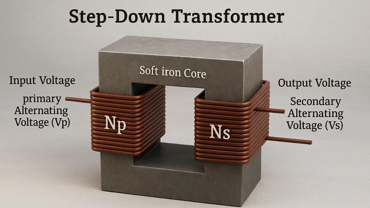
This is the first step in converting from AC to DC voltage. A step-down transformer is a device that converts a high voltage (primary voltage) to a lower voltage (secondary voltage).
A step-down transformer has two windings (coil of wire); primary winding and secondary winding. The primary winding has more turns of wire than the secondary winding.
The primary winding is connected to the main line of AC voltage, while the secondary winding is electromagnetically
Step-down transformers could be broken down into three categories:
Single phase step-down transformer
A single phase transformer reduces input voltage (and, correspondingly, current) so that it produces voltage (as well as, current) output lower than input voltage.
Center-tapped step-down transformer
A center-tapped transformer has a primary coil and a secondary coil that has a center tap, allowing the output voltage level to be a center split (such as 12V to 0 to -12V); and
Multi-tapped step-down transformer
A multi-tapped transformer uses multiple taps on the secondary coil, allowing the transformer to produce numerous desired output voltages (e.g – 0-12 volts and 0-18 volts due to the multiple tap options).
The output from the transformer then feeds a rectifier circuit for further processing.
Rectification
The second phase in the AC-DC voltage conversion path is rectification. This specifies the overall conversion process whereby AC voltage is converted to its equivalent DC voltage.
A rectifier does this. A rectifier is an electronic circuit, and consists of diodes.
Rectifiers are grouped into two groups: controlled and uncontrolled. Controlled rectifiers are formed using SCR’s (Silicon Controlled Rectifiers) or thyristors; uncontrolled rectifiers are made up of diodes. Other types of rectifiers are distinguished by half-wave or full-wave rectifiers.
Half-wave rectifier circuits operate by using one diode to convert/distort half of the AC input signal to a pulsating DC output while discarding the other half of the AC input signal. There are two distinct types of half-wave rectifiers:
Positive Half-Wave Rectifier: This type of rectifier circuit converts the positive half cycle of the AC into direct current (DC) with the negative half lost.
Negative Half-Wave Rectifier: This type of rectifier circuit converts the negative half cycle of the AC into DC while losing the positive half.
Three-phase rectification (also known as polyphase rectification) involves three single phase rectifiers connected together when single-phase rectifiers do not provide enough power. The years passed since in the design of three-phase multi-phase rectifiers.
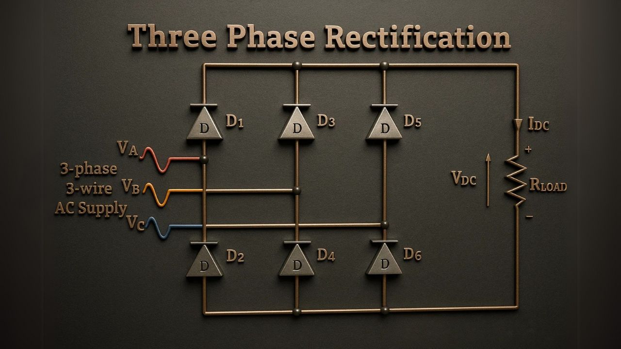
The design purpose of multi-phase rectifiers is for the reduction of harmonics within three-phase systems. Multi-phase rectifiers are generally two 6-pulse rectifiers in series with a total of 12 diodes feeding a DC bus.
Current from the three phases which are 120 degrees apart in time creates a staggering effect giving a quality waveform and cancelling the 5th and 7th harmonics (making the 11th harmonic the dominant harmonic), keeping voltage harmonic distortion (and current too) in the acceptable range.
The multi-phase rectifier design allows for an extended harmonics cancellation (18-pulse rectifier) as there are three 6-pulse rectifier segments, but as each segment adds the price of rectifiers and space also does.
Full wave rectifier circuits generate DC voltage using multiple diodes to repackage both half cycles (positive and negative) of the AC input into the DC output and in effect double the output voltage. There are two types of full wave rectifier circuits:
Bridge Rectifier
As the name denotes, this has four diodes that will let you convert both the positive and negative half cycles of the AC input into DC output. Since the output voltage produced from this bridge rectifier will nearly be twice a full-wave center-tapped transformer rectifier (full-wave) the cost of a bridge rectifier is less than two full-wave transformers.
Center-Tap Rectifier
The full-wave rectifier circuit used here is linked to a center-tapped transformer and two diodes. Each of the diodes utilizes the half-cycle of the AC input. Therefore, there is power on both halves of the input providing high output and efficiency.
DC Filtration
Our output voltage after rectification is a pulsating DC voltage containing a large amount of ripple content. To smooth out the ripples, these ripples must be refined in a process called DC filtration. Common filters used for DC filtration are capacitor filters, LC filters, choke input filters, and π-type filters.
In a capacitor filter, as the instantaneous DC voltage rises to its peak, the capacitor charges. As the voltage goes down, the capacitor discharges slowly through the regulating circuit.
Regulation
The last step in our power supply is to stabilize the output DC voltage to remain constant using regulation.
Regulation maintains the output DC voltage constant which can fluctuate with any changes in the AC mainline input, load current or any of the other changing variables such as temperature.
There are several types of regulators that can be used in this step:
- Transistor series regulator
- Fixed and variable IC regulators
- Zener
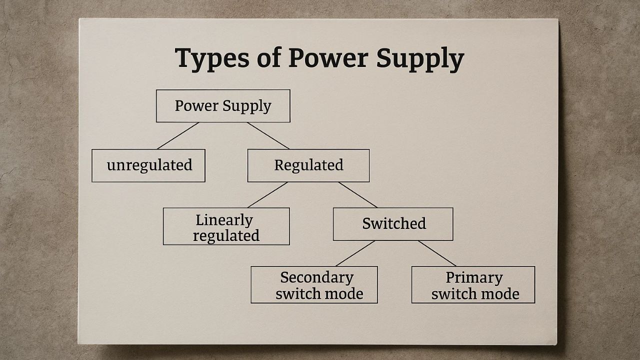
What are the various designs for DC power supplies?
There are two major classifications for DC power supplies, regulated power supplies and unregulated power supplies. Regulated Power Supplies can be further classified as linearly regulated and switch mode power supplies.
Switch mode power supplies can be further classified as primary switch mode and secondary switch mode. The following list explains each type and design of DC power supply.
Unregulated Power Supplies
An unregulated power supply takes the AC mainline input directly to the supply. The AC voltage is reduced by a step-down transformer. The reduced secondary voltage is then rectified to DC.
The output voltage from the rectifier is smoothened through a capacitor. The unregulated power supply does not have a regulator, therefore any changes made on the AC mainline will affect the output voltage directly.
Unregulated power supplies are simple in design, hence their ruggedness, and have an efficiency of 80% typical. They are used strictly in electromechanical applications where output voltages must not be critical such as supplying power to contactors.
The main advantages are:
- Efficiency
- Horsepower/rugged
- Cost
The disadvantages are:
- Bulk size
- Lots of residual ripple
- No DC supply (input)
Linearly Regulated Power Supplies
Linearly regulated power supplies use the AC-DC conversion process in Chapter 3 of the textbook.
The first step in the process is to reduce the AC mains voltage down to a lower level using a transformer, then rectify and filter it. The last step is to regulate the smoothed DC voltage, with a power transistor, to maintain the output voltage constant.
In a linearly regulated power supply, the power transistor varies its resistance.
As current is allowed to flow through the power transistor, the energy loss occurs. The lost energy is dissipated as heat; this must be considered for ventilation in the power supply. Due to these energy losses, linearly regulated power supplies usually have an efficiency of about 50%.
They are frequently used in applications that demand very accurate output voltage such as highly accurate medical devices.
Main advantages are:
- Short regulation times
- Small residual ripple
- Simple circuitry
Disadvantages are:
- Low efficiency
- Large size
- No DC supply (input)
Primary Switch Mode Power Supplies
Primary switch mode power supplies begin with the rectification of the AC mains, followed by filtering and chopping/switching.
Chopping a DC voltage is done by periodically switching it on and off at a frequency of 40 – 200 kHz using a power transistor.
In linearly regulated power supplies, the power transistors act like variable resistors whereas in primary switch mode supplies, they act as switches.
A square-wave AC voltage is generated during the chopping/switching part of the process, which is fed into a high frequency transformer in the secondary circuit and then re-rectified and smoothed.
The chopping rate can be varied to control the load and hence control the energy transferred to the secondary circuit depending on the energy consumption of the load.
The use of high-frequency AC voltage allows the transformers in primary switch mode supplies to be smaller than those needed for low frequency transformations.
Because of this, these power supplies can either be powered by an AC voltage or a DC voltage, or a broad range of both, as the input voltage does not directly affect the output voltage.
There can be a short time buffer of as much as 200 milliseconds, which covers main voltage interruptions.
The buffering time is limited to the capacitor size. The better the power supply is for time buffering, the larger the capacitor will need to be; however, if the power supply is for a small output, a bulky capacitor is less desirable. Ultimately, the power supply needs to be sized accordingly for time buffering and capacitor size.
Primary switch mode power supplies are put into service in both electronic and electromechanical applications in great quantity.
The benefits of a primary switch mode power supply include:
- Small
- Light
- Wide input voltage range
- Easy to regulate
- Very efficient
- Semi regulated input DC supply
- Provides buffering in the event of mains voltage breakdown
The Disadvantages of using a primary switch mode power supply include:
- Complicated circuit
- Pollution to the mains
- High frequency and requires interference suppression.
- Costly
Secondary Switch Mode Power Supplies
Secondary switch mode power supplies are similar to primary switch mode power supplies, as their chopping occurs on the secondary side. The secondary side requires a larger transformer to convert the 50/60 Hz mains voltage, but when this occurs, there is limited mains pollution since the transformer is also filtering the signal.
Benefits of secondary switch mode power supply include:
- Very efficient
- Easy to regulate
- Wide input voltage range
- Low mains pollution
Negatives of secondary switch mode power supplies include:
- Bulk size
- No input DC supply
- Costly
For industrial applications we see primary switch mode power supplies rank the highest as they offer a wide input voltage range, are highly efficient and small.
Applications of a DC/DC Power Supplies
DC/DC power supplies can be found in almost every product as the majority of electronic devices use DC power. Even smaller products that are portable electronic products such as laptop computers and smartphones that are using battery power.
This usage almost always involves products with multiple small circuits that are powered from the battery, or from an external power supply, that may or may not be the same as the DC input voltage required by each circuit, which may be smaller or larger than the battery or external power supply input voltage.
Larger DC/DC power supplies are also used to optimize output power from photovoltaic systems and to charge batteries. There are many DC/DC power supplies such as those used for LEDs that allow for regulated voltage output.
It would be good if we have selected a power supply for a new engineering application or we are upgrading power supplies for old applications and wanted to consider if they are using a ‘good’ power supply, we consider the following; efficiency, regulation time, weight and size, residual ripple, cost and application fields.