What is an Automation System?
An automation system comprises sensors, control elements, and actuator elements to perform a function with little to no human intervention.
Automation is one of the newest technologies available and is a branch of engineering called Mechatronics, which consists of interrelated mechanical, electrical, and electronic systems.
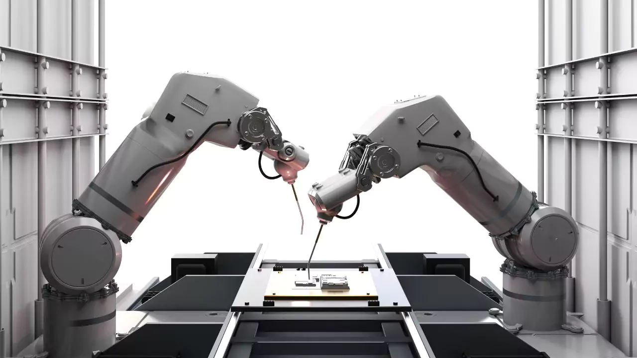
Typically, automation systems are built around previously performed manual operations, including drilling, cutting, and welding. Automation systems usually contain robotic arms capable of controlling the tool that performs the operation.
In applications dealing with process control, automation systems measure and modify the process parameters by controlling equipment associated with the process.
Equipment such as heaters, motors, pumps, and compressors, or by controlling a process path via a valve. Cars are manufactured in different configurations for specific automation tasks.
Key Takaways
- An automation system is an integrating system of sensors, controls, and actuators that are designed to perform a function with little to no human intervention.
- Implementing an automation system represents a tremendous opportunity for cost savings, increased production rate, improved safety, and improved quality. The initial costs associated with implementing automation systems are generally outweighed by the cost advantages from continued utilization of these systems.
- An automation system consists of a device that can receive input (sensor, human-machine interface, etc.), a computing device (processor), and the manipulators that do the actual work (actuator).
- An arm is an assembly of links and joints that have a fixed range of motion. Arms can be Cartesian, polar, cylindrical, SCARA, and articulated.
- End-of-arm-tools (EOATs), also referred to as end effectors, is the tool or operator that encompasses the interaction with the product or process.
- Actuators are the devices that provide force or torque to make things move. There are three classifications of actuators: electric, hydraulic and pneumatic.
Basic Components of an Automation System
An automation system uses an input device (such as sensors or a human-machine interface), a computing device (or processor), and manipulators (or actuators) that are responsible for performing the actual work.
Of these three components, the computing or control system is the most complex and therefore the most important. The control system can be openly described as either open-loop or closed-loop control systems.
Open-loop control systems have controllers that send signals to the actuator based on how things were done in the program only, without regard to an actual response. Closed-loop control incorporates a feedback signal.
Feedback is produced by a sensor that measures, either directly or indirectly, a response produced by the actuator.
This feedback is read by the controller and allows the controller to measure the actual output against the desired response and make any necessary changes in the signals sent to the actuator with respect to the controller’s specified programming. This cycle can be repeated until the desired response is achieved.
The input device can also be a human-machine interface or a sensor. A human machine interface is where the human operator communicates with the controller. The human enters variables or commands to change the desired output.
The sensor measures the output based on various physical properties or electromagnetic properties; such as, pressure, temperature, magnetism, or radiation. It converts the measured physical property into an electronic signal for the controller to read, interpret and use.
Actuators create the actions. An actuator is composed of a driver and an assembly of joints and links. A driver will provide the force or torque needed to move the links connected by joints.
Drivers can take on forms of electric, hydraulic, or pneumatic types. Electric actuators can be categorized as motors or solenoids in which the electric energy is turned into a mechanical output.
Hydraulic and pneumatic types will typically use fluid pressure that is compressed on some type of piston, cylinder, vane, or lobe.
All of these basic systems can also be considered electric in their simplest forms because the fluid is controlled by the open and closing of solenoid valves.
The links of a mechanical system can move relative to one another with respect to the degrees of freedom permitted by the joint. Degrees of freedom refer to the variations of movement permitted for the links in a three-dimensional environment.
Freedom constitutes six degrees of freedom; three translation (up and down, left and right, forward and backward), and three rotation (pitch, yaw, or roll).
To keep these systems simple, joints are normally designed for having only one or two degrees of freedom because a very movable arm is more difficult, costly, and impractical.
Arm Configurations
The arm is where the end-of-arm tools are mounted. An arm consists of an assembly of links and an assembly of joints, including a fixed range of motion. A link is a rigid, but flexible, component that is intended to transfer force.
These links are each connected by joints and can be categorized as either revolute or prismatic. Controllable joints permit movement in a circular manner, while prismatic joints permit movement in a translational manner.
The links and joints determine the degrees of freedom or range of motion of the arm. When configuring the arm, you will have three options.
Cartesian Robot
A Cartesian robot consists of three prismatic joints. The term Cartesian is derived from the three-dimensional Cartesian coordinate system with dimensions of X, Y, and Z.
This is the most foundational type of arm because determining the positions to move the end effector is simple.
This is appropriate when only movement at right angles is required, and rotation of the end effector is not needed. An example of a Cartesian robot is a gantry machine.
Polar Robotic Arm
Polar robotic arms can also called spherical robots. The joint range of motion can be imagined as a sphere, where the radius is the length of the link from the second revolute joint to the end effector.
This link may be extended, using a prismatic joint. So, a polar robotic arm consists of two revolute joints and one prismatic joint.
Cylindrical Robotic Arm
The cylindrical robotic arm has one revolute joint and two prismatic joints. The revolute joint is at the base and permits the linking of the arm to rotate around its axis which creates the cylindrical range of motion.
The prismatic joints can extend, which can be visualized as changing the height and radius of the cylinder.
Selective Compliant Articulated Robot Arm (SCARA)
a SCARA is a robot that has an arm that is compliant or flexible from horizontal left to right in the X-Y plane but is rigid from vertical up to down in the Z-axis, which characterizes its “Selective Compliant” feature.
Its “Articulated Robot Arm” is similar to that of human arms with two links at one end by a joint, this allows the robotic arm to extend or fold.
Articulated or Anthropomorphic Robot
This robot has two more degrees of freedom (example movement) at the end effector, unlike SCARA robots.
Articulated robots also has arms that have a revolute joint at one end connected at the base, as SCARA robot, but there is no vertical linear guide. One arm is attached to a swivel joint with a fixed base which allows movement for flexibility.
What are End-Of-Arm-Tools (EOAT) in automation System?
End-of-arm-tools (EOAT), also known as end effectors are components designed to interact with its products or processes. Most EOATs are grippers; they handle, grasp, lift, drop, transfer, or reorient objects, in a variety of ways.
There are grippers categorized as impactive (mechanical jaws), ingressive (needles), astrictive (vacuum and magnetism), and contigutive (adhesion). EOAT is also designed and manufactured specifically for tasks such as milling, welding, etc.
Mechanical Grippers
These are used for basic pick and place robotic systems. Grippers have one set to three sets of mechanical jaws driven generally by servo motors or pneumatic actuators.
These jaws consist of single line, connected to the wrist through a revolute or prismatic joint. To control the gripping forces while using servo motors, feedback is developed by strain gauges or the current used by the motor.
For grippers that use pneumatic actuators, the gripping force can be increased without damaging the item because of the compression of air.
The jaws can be designed as forks, fingers, parallel plates, or surfaces corresponding to the payload. If the surfaces are lined with compressible high friction materials, a firmer grip can be attained.
Vacuum or Suction Cups
These are utilized for picking objects with smooth surfaces such as films, glass, and plates. One of the common ways of creating a vacuum is to apply a venturi that supplies compressed air. An array of suction cups could be used, to have a greater suction force. Vacuum EOATs can be cleaner than mechanical grippers and allow for some positional deviation. This type of EOAT is not useful for rough, porous, or irregular surfaces. Also, the object may slip out of the suction cup when accelerated too much.
Magnetic Grippers
These types of EOATs utilize electromagnets to lift ferromagnetic objects. Permanent magnets are also a potential option as it does not use power. However, it needs a mechanical device for removing the item acquired.
Electromagnets are commonly used because it is straight-forward to operate, thus allowing the object to be lifted or released by simply supplying or cutting power to the electromagnet.
While there is the restriction of using them only on ferromagnetic materials, they make the parts magnetic which is a problem. You cannot accelerate them too quickly since the attached object can slip off.
Inflatable collars and cylinders
An inflatable collar can be viewed as a looped elastomer tube that is supported by both rigid structure on its outer periphery. It grips the object by expanding the tube while releasing which is when it deflates. Inflatable collars (and cylinders) are used for two-dimensional gripping of tubular or cylindrical products.
Needle grippers
These perform a gripping action by penetrating their object or bulk with needles or hackles/weapons. These EOATs are usually static, meaning there are no moving links or joints.
Needle grippers are good for handling porous or fibrous objects i.e. textiles, carbon and glass fibers where small penetrations are not a problem.
Adhesive grippers
As the name indicates, adhesive grippers grasp your product with surface adhesion. A special type of adhesive is applied to a pad or plate to contact the product to be lifted.
The main advantage to adhesive grippers is their ability to operate without air or power supply. However, they are limited with handling light objects, and do lose their gripping effectiveness over time.
Tools (Permanent and Interchangeable)
Tools can also be mounted at the outermost link of the wrist instead of an gripper. The Tool can be attached permanently or can be interchangeable.
Common tools for end effectors include screwdrivers, wrenches, drills, rotating cutters, lasers, water jet nozzles, paint spray nozzles, welding electrodes, and solders.
Alternative specialized end effectors could be inspection systems with sensors mounted to them; an example of this is a camera or other optical devices to do non-contact testing and/or 3D measurements.
The resulting measurements are correct in the order of tenths of a millimeter because of the inherent repeatability, precision, and accuracy associated with robotic systems.
Existing end effectors may also adapt over time based on changes due to new product demands, system upgrades, or obsolescence of components. During determination of applicability of the new end effector, there are several important considerations:
- The weight of the new end effector;
- The positional and angular accuracy with respect to the workpiece;
- The force and torque used by the end effector;
- The rigidity;
- The adapter/coupling/quick-release;
- The feedback control and sensors mounted onto the end effector;
- The auxiliary system.
Anthropomorphic and Adaptive Grippers
Compared to mechanical grippers, anthropomorphic grippers have more complex links and joints. Mechanical grippers normally consist of one link and joint connection to the wrist, which is usually based on a revolute or prismatic joint application.
In contrast, anthropomorphic grippers are composed of two or more links connected by revolute joints.
Anthropomorphic grippers can be configured for two- or three-dimensional gripping, by having two or three sets of fingers, respectively. Each finger functions by giving independent actuation to a finger and utilizing sensors for near proximity sensing and grip strength.
Anthropomorphic and adaptive grippers are particularly advantageous in applications where objects vary frequently such as in sorting and multiple product line packaging operations.
What do actuators do in automation?
Actuators are mechanical components that provide traction or torque to create motion. The actuator is coupled to the links and joints using tendons, gears, chains, cams, or shafts collectively called the actuation system. Actuators are generally classified into three categories; electrical, hydraulic, and pneumatic.
Electric Actuator
Electric actuators are the most common actuators used for industrial robots. The most common electric actuator is the servo motor which is powered by a DC power supply.
Rotational movement developed by the servo motor can be transferred into linear motion using mechanical elements such as belts, cables, or chains.
Electric actuators capable of generating linear motion are also available in the form of a linear motor and solenoids. The principal types of electric actuators are summarized below:
Servo motors
This type of electric actuator relies on a closed-loop or feedback system that processes an output signal, controlling their position, speed, and acceleration.
The Servo motors utilized in the servomechanism can be a brushed DC motor, brushless DC motor, AC motors and even linear motors.
Each servomechanism has a sensor, transducer, or potentiometer called an encoder that measures the position and speed of the motor and produces an electronic signal.
The signal, whether it be digital or analog, is fed into an amplifier and controller, which then changes the voltage or frequency of the electric power supplied to the motor.
Stepper Motors
Stepper motors are amazing because they do not require a feedback loop like the servomotor. Instead, they rely on continuous energizing and de-energizing of stator poles that pull the poles of the rotor.
The stator, which has poles energized separately to pull the rotor poles, creates the stepping rotation (indexed rotation) of the gear head or rotating arm whilst the rotor is made from laminated ferromagnetic material noted for having a different number of poles from the stator.
The reason there is a difference in the number of poles of the rotor and the stator is to allow for only one set, or one pair of poles to be attracted at any one time.
The controller and amplifier will power the poles in accordance to the programmed speed of the motor and to initiate action of the actuator.
These motors are a simpler design than those of the servomotor, but allow less power. The motors may slip if the load exceeds capacity. Since they do not have any feedback built into the design, there is no way to recover from the deviation.
Pneumatic Actuators
Pneumatic actuators operate on compressed air. Pneumatic actuators are powered by compressed air pressure to operate – most commonly around 6 to 10 bars of pressure. Essentially, the flow of compressed air is controlled by solenoid valves.
The commonly seen types of pneumatic actuators consist of cylinders or rams. A pneumatic cylinder has a piston that extends or retracts upon the application of pressure of the air in the cylinder.
One side of the piston is connected to a rod which couples to the robot arm. There are other ways to couple devices or mechanisms other than those previously discussed.
These include other types of devices such as cables and magnets. The amount of force that is developed will depend on the air pressure along with the effective area of the piston.
Pneumatic cylinders can be single acting or double acting. A single acting cylinder has only one inlet port and compressed air can push the piston in one direction and then an external force is used for the return stroke. The external force can be from spring force or gravity.
A double acting cylinder has two ports at both ends of the cylinder that are the inlet port and the exhaust port. Compressed air can be supplied to one end and allowed to exhaust at the other end.
This design allows the piston to function in both push and pull in two different directions. There is another type of pneumatic cylinder although not as common, is called a telescoping pneumatic cylinder.
A telescoping pneumatic cylinder is comprised of nested shells that extended when a compressed air source is introduced. Telescoping pneumatic cylinders can be single acting or double acting.
Pneumatic motors are used to create rotary motion using compressed air. The most common pneumatic motor being used today are rotary vanes and turbines. A rotary vane motor creates a rotation by means of positive displacement as air flows by the rotor.
A turbine motor creates a rotation by means of the kinetic energy of the air flowing by the motor. Apart from pneumatic cylinders and pneumatic motors, there are many other different forms of pneumatic actuators, such as tubes, bellows and diaphragms.
Even though they are constructed and configured differently they all operate with the same principled as pneumatic cylinders and pneumatic motors.
Hydraulic Actuators
Hydraulic actuators operate similarly to pneumatic actuators by force. The differences are mainly in the force output, structural integrity, fluid circuit, and whether the actuator can be servo-controlled.
Hydraulic actuators can output very large forces to handle heavy payloads because hydraulic fluids (or oil) are incompressible. These actuators can handle pressures up to 130 bars.
Because of the pressures involved, hydraulic actuators are made from thick rigid metals. The rams and pistons are surface treated to protect them and keep the hydraulic fluid from leaking.
Pneumatic circuits are usually open, meaning the compressed air is not recirculated back in the system. Hydraulic circuits return the fluid back to the pumping unit, the oil is filtered and cooled and then circulated back to the system. When fluid is compressed to higher the pressure it will begin to heat-up and accelerate its degradation.
One other advantage of hydraulic actuators is that they can be servo-controlled. Pneumatic actuators can only extend or retract completely. Hydraulic actuators have the ability to be servo-controlled, making it possible to control the length and speed of extension.
Advantages of Automation System in Industry
More Consistent Production
A robotic system designed efficiently can expedite the production time needed in the process by controlling complicated motions. Faster output means increased production volume, resulting in more profit.
Faster action requires enough force for the driver, and motion along the linkages or joints must be smooth motion with no unnecessary transition. Importantly, the speed processing of a computer is superior because it is more efficient than human.
Humans may process in more complex ways than computers, but when human error, days of work, and breaks are considered, computers perform better.
Increased Repeatability
A production line operates efficiently due to the repetition of the same sequence of movements that can be thought of as having been in some way “programmed” into the operator carrying out the work.
The operator has very little decision making where the movements are largely governed by a predetermined, explicit set of instructions.
These repetition-based movements can be broken down into movements that are simply translations and rotations that can be programmed into the robot, and since the actuators are designed for a consistent direction of movement, increase repeatability.
Precision and Accuracy
As stated previously, the actuators are required designed for that consistent range of movement. The nature of the actuator’s movement will not change except for a feedback signal, or change in the control variables.
The automation system as a whole can be calibrated to produce the same output with minimal or no deviation.
Increased Product Quality
The big point about automated systems is that products are made in one consistent way. Human error and subjective judgment should not come into play as the automated system is making decisions from a logic stand point, and monitor whether that condition meets the desired output.
Verification can be obtained almost instantaneously, and can be done through feedback systems that are more efficient than any human.
Better Working Conditions
Processes that include extreme temperatures, excessive pressures, high forces, fast movements, and toxic materials represent a possible safety hazard to personnel. with automation, a robot can complete the unsafe tasks remove the threat of injury or even death.
Lower Operating Costs
In addition to greater profit margins based on good quality and therefore a consistent high production rate, process owners can benefit economically from less wastage of raw material, and lower manpower costs.
Less wastage is achieved when automation systems have to use manual feeder tracks where raw material is consistent, In this case, all of the feed amount can easily be optimized through programming.
As for the manpower, more than one set of hands can be replaced by one robot, and in the long run will have offset what was considered a major upfront investment cost at the outset of building the automated system.
Disadvantages of Automation System
High Investment Cost
High capital expense is probably the biggest factor that stops process owners from setting up an automated system. Besides the sensors, controllers, and actuators, an automation system contains a lot of different auxiliary systems including the power supply, compressed air system, hydraulic system, and lubrication system.
Robotic systems starting costs can be from hundreds of dollars to millions of dollars to automate a process depending on the degree of automation required.
More Maintenance Required
Automated systems may not fatigue as do the human operators, but with any continuous operation of machinery, there will be wear on components.
Regular maintenance will be carried out to check or prevent any issues that will cause a shutdown in the automated process, and to maintain its optimum level of performance and service life.
Less Versatility
In most cases, an automated system cannot be easily reconfigured. Having modularity, or programmability is an added expense in equipment.
Robots in effect cannot think, they can only respond to act on specific instructions provided by the arm the robot was programmed to use; any work or process that exceeds their programmed ability can cause chaos and unpredictability, even causing a system shutdown.
In many cases, human operators can assess those conditions and take action to attenuate any sort of problematic situation.